IOM-Ranger
2
SECTION III
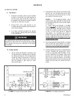
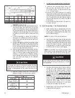
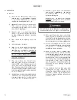
FIGURE 1:
Typical Control Valve Station
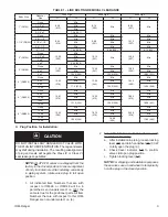
FIGURE 2:
Line Bolting Clearance
_
M ANUAL BYPASS
BLOCK
DRAIN
DRAIN
CONTROL
VALVE
BLOCK
SIG
LOA
IAS
AIRSET
I/P
PO SIT
V
2. If the pipe reducers, elbows, noise at ten u a tion
de vic es, etc., are located before and/or after
the valve body, keep these pieces as close
as practical to the valve body.
NOTES:
1. For flangeless design, allow
suf fi cient clear ance up stream from valve body
for line bolt in ser tion and removal. See Figure
2 and Ta ble 1.
2. Undue piping stress/strain or bending
torques may not be transmitted through the
control valve body. One pipe (inlet or outlet)
should be anchored rigidly for piping that
is “hot” or “cold’” with respect to ambient
tem per a ture; the remaining pipe (inlet or
outlet) should be supported and guided to
ensure uni di rec tion al expansion/con trac tion.
Prop er ly align prior to installing valve with
required flange bolting.
3. Clean the piping of all foreign debris, including
chips, weld scale, weld splatter, oil, grease,
sand or dirt, prior to installing the control valve.
THIS IS AN AB SO LUTE RE QUIRE MENT!
4. Field hydrostatic testing the completed piping
system, including the Ranger QCT valve,
to the max allowable CWP indicated on the
valve’s name plate is acceptable. If hydro test
pres sure is to exceed this limit, the Rang er
QCT must be removed before such test ing.
Be fore pres sur iza tion, the valve plug must be
rotated out of the seat if of reverse, ATO-FC
action.
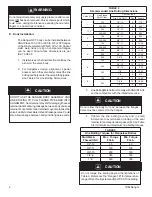
WARNING
The valve/actuator unit should not be used as a “step” to
support personnel. Failure to comply may cause leak age
at the flange/valve body joint, especially for flangeless
body design.
III. INSTALLATION
A.
Orientation:
1. Preferred orientation when valve is installed
in either a horizontal or vertical pipeline is
with the valve stem horizontal. Valves may
be installed with the stem any where between
horizontal or vertical for all sizes.
2. Ranger QCT valve with actuator is not
rec om mend ed for installation with the actuator
ori ent ed down wards.
3. In no case is additional weight to be applied
to the actuator subassembly when installed
in any orientation.
B.
Piping
System:
1. It is recommended that the control valve unit
be installed with a double-block and bypass
as indicated in Figure 1. This arrangement is
necessary when main te nance is to be done
on the valve body. Valve must be removed
from the pipeline to gain access to unit’s
internal trim parts.


