IOM-Ranger
4
CAUTION
Do not torque line bolting beyond the limitations of
Table 3. Ref er ence the “Ranger-TB” for tem per a ture
range of Opt-7A alloy steel and Opt-7C SST line bolting.
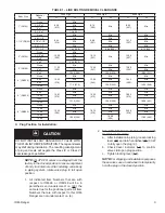
TABLE 2
Recommended Line Bolting Dimensions
Valve Size
Line Flange
ANSI Class
Tie Rod Studs
Dia.-Thd. UNC
Qty.
Length
1"
150
1/2"-13
4
7.75"
300-600
5/8"-11
4
8.00"
1-1/2"
150
1/2"-13
4
7.75"
300-600
3/4"-10
4
9.00"
2"
150
5/8"-11
4
9.25"
300-600
5/8"-11
8
9.25"
3"
150
5/8"-11
4
10.50"
300-600
3/4"-10
8
12.25"
4"
150
5/8"-11
8
11.50"
300
3/4"-10
8
12.25"
600
7/8"-9
8
14.25"
6"
150
3/4"-10
8
13.75"
300
3/4"-10
10
14.75"
3/4"-10
4
5.50
600
1"-8
10
16.50"
1"-8
4
6.75"
8"
150
3/4"-10
8
15.50"
300
7/8"-9
10
16.50"
7/8"-9
4
6.25"
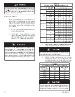
3. Line Bolting Material must comply with ANSI B16.34
and be compatible with the in tend ed service.
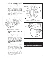
4. Tighten the line bolting evenly and in small
in cre ments to avoid uneven load ing of the seal
retainer (3) and seal retainer gas ket (9). See Ta ble
3 for minimum and max i mum line bolt ing torques.
CAUTION
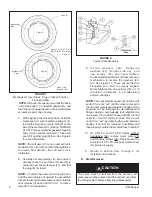
Do not allow the body to “cock” between the flanges.
Valve must be centered on the flanges.
D. Body Installation:
The Ranger QCT body can be installed be tween
ANSI Class 150, 300 or 600 lb. RF or FF flanges
or their ISO equivalent of PN20, 50 or 100. Socket
weld, weld neck or slip on companion flanges
can be used. Face-to-face di men sions are per
ISA 75.08.02.
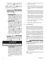
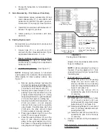
1. Install valve so the flow direction matches the
arrow on the valve body.
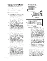
2. For flangeless design alignment, special
boss es cast on the valve body contact the line
bolting and help center the valve in the pipe line.
See Table 2 for Line Bolting Di men sions.
CAUTION
DO NOT USE THE RANGER BODY ASSEMBLY AND
LINE BOLTING TO PULL FLANGE PIPE ENDS INTO
ALIGNMENT. Seal retainer may shift, dam ag ing the seal
retainer gasket allowing leakage between body and seal
retainer. Movement of seal retainer may compromise the
valve's ability to meet stated shut-off leakage rates. Could
also allow leak age between body and flange pipe ends.
WARNING
Do not adjust temporary air supply pressure after cover
plate (20) has been removed. Valve contains parts which
could move during maintenance exposing hand and/or
fingers to a hazardous condition.
TABLE 3
Line Bolting Torques for Flangeless Bodies
Stud Size &
Thread UNC
Max. Torque
Ft-Lb.
Min. Torque
Ft-Lb.
1/2"-13
65
60
5/8"-11
120
100
3/4"-10
200
140
7/8"-9
320
160
1"-8
440
180


