IOM-Ranger
9
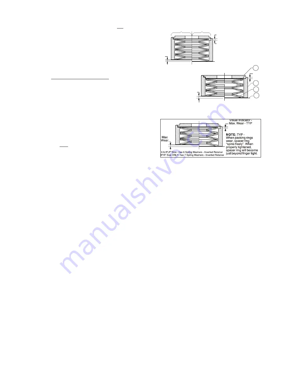
Max Wear
Max
Wear
29
28
2
1
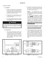
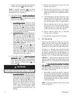
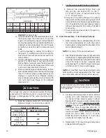
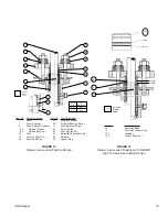
2", 3" & 4" RANGERS ONLY
6 Spring Washers
Non-Inverted Retainer
FIGURE 9
Ranger Live-Loaded Packing Design
Initial Setting
Position - TYP
Maximum Wear Position
-Adjustment Required - TYP
Max Wear
0.050"-0.060"
- TYP
Max
Wear
1" & 1-1/2" RANGERS ONLY
8 Spring Washers - Inverted Retainer
i.
Pull yoke (12), packing flange (14), pack ing
follower (15) and follower bushing strip
(16) off over end of stem (7). Re place
packing follower (15) if sig nif i cant ly
cor rod ed. Always replace fol low er
bushing strip (16) when of standard
construction.
(NOTE:
When Opt-38HT
high tem per a ture pack ing is sup plied,
the packing fol low er (15.1) con tains a
pressed-in car bon bush ing (15.2) that is
not field re place able and must be sup plied
as a packing follower (15) sub as sem bly.)
j. Loosen stem retainer screw (17) by
ro tat ing CCW (viewed from above screw
head) 2-3 rev o lu tions to check for trapped
fluid. After all fluid is vented, remove screw
(17).
k. Rotate stem (7) CW when viewed from
actuator end of stem (7) to close plug (6).
l. Withdraw stem subassembly (7), retainer
sleeve subassembly (8) and packing set
(13) out of body (1).
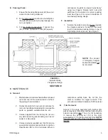
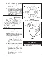
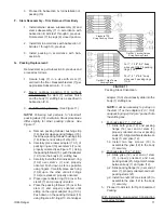
NOTE:
If difficulty is encountered in re mov ing
the stem subassembly (7), use a puller
as sem bly. See Figure 10. Hold the double nut
with a wrench to prevent rotation of the stem
as this could damage the seals if the trim is
still in the valve body (1). Use the single nut
to jack the stem sub as sem bly (7) out.
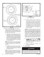
1. Remove the actuator as sem bly (AA) from the
valve body as sem bly (BA). Refer to Ac tu a tor
main te nance manuals IOM-48 or 148.
2. Secure body (1) in a vise with the stem (7)
hor i zon tal to the floor. Place matchmarks
be tween yoke (12) and body (1) to assist in
final orientation when re-assembled.
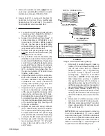
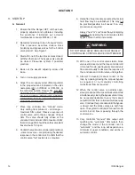
3. For live-loaded construction:
a. Loosen both packing flange nuts (22) until
clearance exists between the bot tom of
the nut (22) and the retainer (28).
b. Spacer ring (29) should “spin freely”. If
stacked mech a nism (27)(28)(29) is not
loose due to corrosion, debris, packed
dirt, etc., tap the spacer ring (29) lightly
while at tempt ing to pry up the spacer ring
(29) bottom with a thin flat tool.
c. Remove both packing flange nuts (22)
only after the live-loaded mechanism (27)
(28)(29) is “free” and loose.
d. Pry up both live-loaded mechanisms (27)
(28)(29) one side at a time. Carefully lift the
mechanism (27)(28)(29) over the pack ing
stud (21) ensuring that the Belleville spring
washers (27) are not dropped in removal,
preventing a de ter mi na tion of washers'
(27) orientation one-to-the-oth er. Set
the two mech a nisms (27)(28)(29) down
together, side by side.
e. Inspect the retainers (28) for ori en ta tion.
Both of the retainers (28) should have
the same orientation. Improper/differing
ori en ta tions will cause un bal anced
loading of the packing rings (13). See
Figure 9 for proper ori en ta tion.
f. Inspect both spring washer (27) stacks
for proper orientation by carefully lifting
off the spacer ring (29) and retainer (28),
exposing the spring washer (27) stack.
Each stack of spring washers (27) should
be oriented the same. Improper/differing
orientation will cause unbalanced load ing
of the packing rings (13). See Figure 9
for proper orientation.
g. Replace all Belleville spring wash ers
(27) if there are any signs of corrosion.
It is recommended that spring washers
be replaced in full sets. The spacer rings
(29), retainers (28), as well as the packing
studs (21) should be re placed if corroded.
h. Remove yoke (12) bolting by removing
two cap screws (19) on 1", 1-1/2" and 2"
sizes, or two nuts (22) on the 3", 4", 6"
and 8" sizes.


