Rev. 03-2004
Part 1. Operation Manual
PAGE 1-19
FrontLoad Bill Validator Series - Operation and Service Manual
MODULAR
SYSTEM
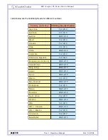
Depending on the bill type, the following Sense-a-Click
™
part numbers are used:
y
c
n
e
r
r
u
C
s
k
a
P
r
o
s
n
e
S
k
c
i
l
C
-
a
-
e
s
n
e
S
r
o
f
r
e
b
m
u
N
t
r
a
P
l
e
d
o
M
o
w
t
f
o
t
e
S
s
e
l
u
d
o
m
r
e
p
p
U
e
l
u
d
o
m
e
l
u
d
o
m
r
e
w
o
L
a
n
it
n
e
g
r
A
R
A
4
0
7
1
-
S
L
F
U
4
0
7
1
-
S
L
F
L
4
0
7
1
-
S
L
F
A
a
il
a
r
t
s
u
A
U
A
4
0
7
1
-
S
L
F
U
4
0
7
1
-
S
L
F
L
4
0
7
1
-
S
L
F
A
li
z
a
r
B
R
B
4
0
7
1
-
S
L
F
U
4
0
7
1
-
S
L
F
L
4
0
7
1
-
S
L
F
A
a
d
a
n
a
C
A
C
1
0
8
1
-
S
L
F
U
1
0
8
1
-
S
L
F
L
1
0
8
1
-
S
L
F
A
e
li
h
C
L
C
4
0
7
1
-
S
L
F
U
4
0
7
1
-
S
L
F
L
4
0
7
1
-
S
L
F
A
a
n
i
h
C
N
C
5
0
7
1
-
S
L
F
U
5
0
7
1
-
S
L
F
L
5
0
7
1
-
S
L
F
A
a
i
b
m
o
l
o
C
O
C
4
0
7
1
-
S
L
F
U
4
0
7
1
-
S
L
F
L
4
0
7
1
-
S
L
F
A
c
il
b
u
p
e
R
n
a
c
i
n
i
m
o
D
O
D
4
0
7
1
-
S
L
F
U
4
0
7
1
-
S
L
F
L
4
0
7
1
-
S
L
F
A
)
o
r
u
E
(
n
o
i
n
U
n
a
e
p
o
r
u
E
U
E
4
0
7
1
-
S
L
F
U
4
0
7
1
-
S
L
F
L
4
0
7
1
-
S
L
F
A
n
i
a
t
i
r
B
t
a
e
r
G
B
G
4
0
7
1
-
S
L
F
U
4
0
7
1
-
S
L
F
L
4
0
7
1
-
S
L
F
A
g
n
o
K
g
n
o
H
K
H
5
0
7
1
-
S
L
F
U
5
0
7
1
-
S
L
F
L
5
0
7
1
-
S
L
F
A
o
c
i
x
e
M
X
M
5
0
7
1
-
S
L
F
U
5
0
7
1
-
S
L
F
L
5
0
7
1
-
S
L
F
A
d
n
a
l
a
e
Z
w
e
N
Z
N
4
0
7
1
-
S
L
F
U
4
0
7
1
-
S
L
F
L
4
0
7
1
-
S
L
F
A
s
e
n
i
p
p
il
i
h
P
H
P
4
0
7
1
-
S
L
F
U
4
0
7
1
-
S
L
F
L
4
0
7
1
-
S
L
F
A
a
i
s
s
u
R
U
R
4
0
7
1
-
S
L
F
U
4
0
7
1
-
S
L
F
L
4
0
7
1
-
S
L
F
A
a
c
i
r
f
A
h
t
u
o
S
A
Z
4
0
7
1
-
S
L
F
U
4
0
7
1
-
S
L
F
L
4
0
7
1
-
S
L
F
A
e
n
i
a
r
k
U
A
U
4
0
7
1
-
S
L
F
U
4
0
7
1
-
S
L
F
L
4
0
7
1
-
S
L
F
A
A
S
U
S
U
4
0
7
1
-
S
L
F
U
4
0
7
1
-
S
L
F
L
4
0
7
1
-
S
L
F
A
a
d
a
n
a
C
+
A
S
U
A
C
S
U
1
0
9
1
-
S
L
F
U
1
0
9
1
-
S
L
F
L
1
0
9
1
-
S
L
F
A
a
l
e
u
z
e
n
e
V
E
V
5
0
7
1
-
S
L
F
U
5
0
7
1
-
S
L
F
L
5
0
7
1
-
S
L
F
A
d
n
a
lt
o
c
S
L
S
4
0
7
1
-
S
L
F
U
4
0
7
1
-
S
L
F
L
4
0
7
1
-
S
L
F
A
o
c
i
x
e
M
+
A
S
U
X
M
S
U
4
0
7
1
-
S
L
F
U
4
0
7
1
-
S
L
F
L
4
0
7
1
-
S
L
F
A
n
i
a
t
i
r
B
t
a
e
r
G
+
A
S
U
B
G
S
U
4
0
7
1
-
S
L
F
U
4
0
7
1
-
S
L
F
L
4
0
7
1
-
S
L
F
A
g
n
o
K
g
n
o
H
+
a
n
i
h
C
K
H
N
C
5
0
7
1
-
S
L
F
U
5
0
7
1
-
S
L
F
L
5
0
7
1
-
S
L
F
A
n
a
t
s
h
k
a
z
a
K
Z
K
4
0
7
1
-
S
L
F
U
4
0
7
1
-
S
L
F
L
4
0
7
1
-
S
L
F
A
Lower Module
Upper Module
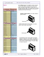
“Sense-a-Click
™
”
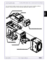
sensor paks are a set of two modules – one upper and one lower. In order to be
compatible with each other, both modules must have the same part and model number.
The Sense-a-Click
™
set is identified by:
- Color and position of the optical sensors;
- Number and position of the Inductive sensors;
- Capacitive sensors;
- Model, which reflects the type of electronics housed within, and determines the
compatibility with other modules.
SENSE-A-CLICK
®
MODULES

