page
1-20
Part 1. Operation Manual
Rev. 03-2004
Bill Acceptor FL Series Service Manual
r
e
b
m
u
N
t
r
a
P
r
e
w
o
P
e
c
a
f
r
e
t
n
I
l
e
d
o
M
r
o
t
c
e
n
n
o
C
y
r
o
m
e
M
h
c
u
o
T
0
1
7
1
-
P
L
F
C
D
V
2
1
)
d
e
t
a
l
o
s
i
-
o
t
p
O
(
P
D
B
L
F
-
C
C
A
o
N
0
1
7
2
-
P
L
F
C
D
V
2
1
)
C
2
3
2
S
R
(
T
E
N
C
C
,
S
P
D
B
-
C
C
A
o
N
0
1
8
2
-
P
L
F
C
D
V
2
1
L
P
I
-
C
C
)
t
n
e
r
r
u
C
w
o
L
e
s
l
u
P
d
e
t
a
l
o
s
I
(
A
o
N
0
1
7
5
-
P
L
F
C
D
V
4
2
)
C
2
3
2
S
R
(
T
E
N
C
C
,
2
2
C
P
G
-
C
C
B
o
N
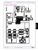
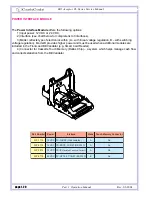
The
Power Interface Module
offers the following options:
1) Input power: 12 VDC or 24 VDC;
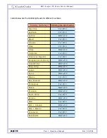
2) Interface (see chart below for complete list of interfaces);
3) Model: reflects type of electronics within (A – with linear voltage regulation, B – with switching
voltage regulation). Model B provides higher power and must be used when additional modules are
included in the FrontLoad Bill Validator (e.g. Smart Card Reader)
4) Connector for Cassette Touch Memory (Dallas Chip) – a system which helps manage cash flow
and collects statistics from the Bill Validator.
POWER INTERFACE MODULE

