page
1-32
Part 1. Operation Manual
Rev. 03-2004
Bill Acceptor FL Series Service Manual
If the position of the mounting screws is different than the position of the mounting holes provided in
the target equipment, then additional frame mounting components may be required.
INSTALLATION
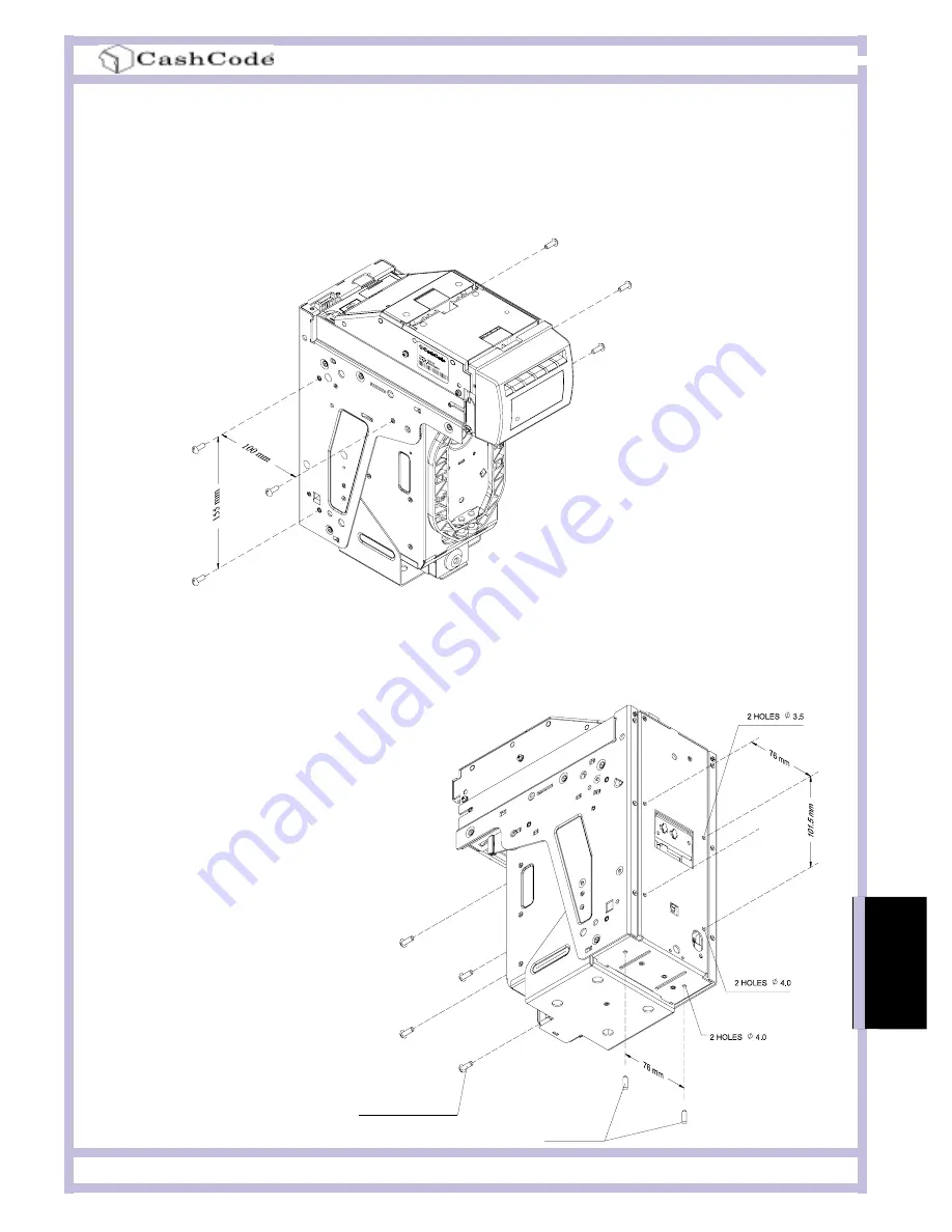
The Bill Validator is installed by using (3) M4 screws on each side of the FrontLoad frame. The
length of these screws should not be longer than required, otherwise they may protrude through the
inside of the frame.
Two locator pins
Four screws M3, Pan Head
The FrontLoad Bill Validator can also
be secured through the holes in the
rear wall of the Housing. In this
case, M3 screws and locator pins
can be used.
For dimensions of the mounting
holes, please refer to the dimen-
sional drawings (page 8 to 13).
INST
ALLA
TION

