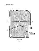
R/P Head
Adjust Screw
CASSETTE MECHANISM ELECTRICAL ADJUSTMENTS
General Remarks
*
Before attempting to adjust the mechanism, wipe clean all tape-contacting surfaces (pinch roller, REC/PB
head, erase head, and capstan), as well as the contact surfaces of the driving parts (motor pulley, flywheel,
pulley, belt, and clutch assembly), with a piece of soft cloth moistened with denatured alcohol. Grease stains
may cause trouble.
*
Never use a magnetized screwdriver for head adjustment.
Equipment Required
*
Oscilloscope
*
Frequency counter
*
Screwdriver (Plastic type)
*
Test tapes MTT-113C (TEAC) or TCC-111N (TEAC)
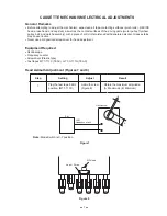
Head Azimuth Adjustment (Figures 7 and 8)
Step
Setting
Adjust
Result
1
Play the test tape 8 KHz
position. (MTT-113C)
Azimuth screw
(Figure 8)
Obtain the maximum amplitude.
(A: Maximum) (B: Minimum)
Figure 8
Figure 7
Note: Mode Switch is X-Y position.
Oscilloscope
A
B
Set
J501
Headphone Jack
7
Summary of Contents for CD-311S
Page 1: ... without price CD 311S CD RADIO CASSETTE PLAYER INDEX Model C Europe Model E Other Countries ...
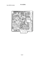
Page 22: ...PCB VIEWS 20 Tuner PCB Top View ...
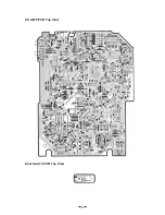
Page 23: ...21 CD AMP PCB Top View Door Switch PCB Top View ...
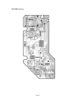
Page 24: ...22 VR PCB Top View ...
Page 26: ...24 Tape PCB Top View ...
Page 27: ...25 LCD PCB Top View ...
Page 34: ...32 IC801 TMP47C422F FR11 ...
Page 48: ...Cassette Mechanism 46 13 1 13 2 13 3 13 4 13 5 13 6 13 ...
Page 49: ...47 Case Unit 14 7 14 4 14 2 14 6 14 3 14 1 15 8 14 8 14 7 14 5 ...
Page 50: ...48 Top Case Unit 15 2 15 4 15 3 15 5 16 15 7 15 6 15 1 14 8 15 8 ...


