– 11 –
2. AC adaptor check
Press "3" button.
Make sure that a value "XXX" shown in the illustration is in
the range of 000 to 3FF.
Press "3" button.
Make sure that a value "XXX" shown in the illustration is in
the range of 000 to 1FF.
Press "0" to end the AC adaptor Check.
3. Memory check
Press "5" button. (ROM check)
Press "1" button.
* Check for "OK" message and sound signal.
Press "0" to end the ROM Check.
Press "6" button. (RAM check)
Press "1" button.
* Check for "OK" message and sound signal.
Press "0" to end the RAM Check.
3:AD1XXX
000 to 3FF
3:AD3XXX
000 to 1FF
6:MEM
5:ROM
OK
OK
TEST 1-9
TEST 1-9
TEST 1-9
Summary of Contents for CTK-4000
Page 1: ...ELECTRONIC KEYBOARD without price CTK 4000 JUL 2008 CTK 4000 Ver 2 Dec 2008 ...
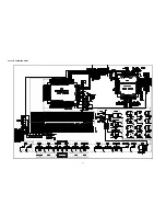
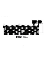
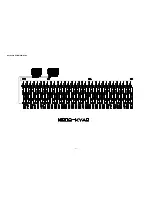
Page 11: ... 9 Keyboard PCB M802 KYA1 Top View Bottom View Keyboard PCB M802 KYA2 Top View Bottom View ...
Page 19: ... 17 SCHEMATIC DIAGRAMS Main PCB M804 MDA1 Not used pin12 to pin15 ...
Page 20: ... 18 Sub PCB M804 PSA1 Not used ...
Page 21: ... 19 Console PCB M805 CNA1 ...
Page 22: ... 20 Console PCB M805 CNA2 Console PCB M805 CNA3 ...
Page 23: ... 21 Console PCB M805 CNB1 Console PCB M805 CNB2 ...
Page 24: ... 22 Console PCB M802 KYA1 ...
Page 25: ... 23 Keyboard PCB M802 KYA2 ...


