background image

MA0800761A

Aug,  1996

Summary of Contents for CTK-520L

Page 1: ...R GUITAR 89 CHOIR STRINGS SPLIT PERCUSSION 90 BASS PIANO 91 BASS E PIANO 92 BASS VIB 93 BASS G GUITAR 94 BASS D GUITAR 95 STRINGS PIANO 96 STRINGS TRUMPET 97 VIBRAPHONE 98 MARIMBA 99 PERCUSSION 100 TO...

Page 2: ...CONTENTS Page Specifications 1 Block Diagram 2 Circuit Description 3 Major Waveforms 6 Printed Circuit Boards 7 Schematic Diagrams 8 Exploded View 14 Parts List 15...

Page 3: ...utput impedance 50 Output voltage 2 V rms MAX Auto power off Approximately 6 minutes after the last operation Power source 2 way AC or DC source AC AC adapter DC 6 AA size Power consumption 7 7 W Dime...

Page 4: ...07 Power Supply Circuit Q301 Q304 D334 D335 Amp IC301 LA4598 Filter L Q306 Filter R Q305 Phone Output DC 9V IN APO Cancellation Signal APO MA0 MA16 MD0 MD7 Sound Source ROM LSI2 MX23C1010MC 12CA45 KO8...

Page 5: ...bootstrap capacitor 3 Ch1 OUT Out Channel 1 output 4 VCC In 9V source 5 Ch1 N F In Negative feedback input 6 Ch1 IN In Channel 1 input 7 D C Terminal for a decoupling capacitor 8 Pre GND In Ground 0V...

Page 6: ...ong Bank Part Select One Key One Key Demo K11 Step 1 Step 2 Step 3 Fingered Casio Chord Normal Off LED MATRIX LX0 LX1 LX2 LX3 LX4 LX5 LX6 LX7 LY0 D4 D3 C3 C2 G 2 F 2 D 2 C 2 LY1 C4 E3 B2 D2 A 2 C 3 D...

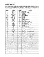
Page 7: ...50 AGadc In Ground source for the internal ADC 51 ANI Not used Connected to ground 52 AVadc In 5 V source for the internal ADC 53 NC8 Not used 54 MOD0 In Mode selection terminal Connected to 5 V 55 56...

Page 8: ...bootstrap capacitor 3 Ch1 OUT Out Channel 1 output 4 VCC In 9V source 5 Ch1 N F In Negative feedback input 6 Ch1 IN In Channel 1 input 7 D C Terminal for a decoupling capacitor 8 Pre GND In Ground 0V...

Page 9: ...signal RH5VL40AA pin 1 4 Sound signal R ch JH connector pin 3 5 Sound signal L ch JH connector pin 1 6 LED drive signal LX0 MSM6755B 07 pin 88 3 Clock MSM6755B 07 pin 32 7 LED drive signal LY0 MSM6755...

Page 10: ...7 PRINTED CIRCUIT BOARDS Sub PCB KDM446 MA2M Top view Main PCB JCM446 MA1M Bottom view Top view 2 4 5 1 3 6 7...

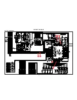
Page 11: ...8 SCHEMATIC DIAGRAMS Main PCB JCM446 MA1M 5 1 6 7 2 3 4...

Page 12: ...9 Sub PCB KDM446 MA2M...

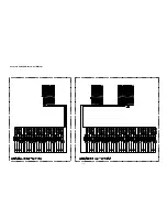
Page 13: ...10 Keyboard PCBs KDM6111K KY1M KY2M...

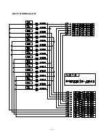
Page 14: ...11 LED PCB KDM446 LD1M...

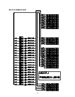
Page 15: ...12 LED PCB KDM446 LD2M...

Page 16: ...13 LED PCBs KDM446 LD3M LD4M LD5M KDM446 LD5M KDM446 LD4M KDM446 LD3M...

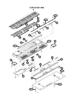
Page 17: ...1 2 3 8 9 5 10 6 7 4 11 12 13 13 14 15 16 17 18 19 20 21 22 R 1 R 3 R 4 R 5 R 2 R 6 R 7 R 7 EXPLODED VIEW 14...

Page 18: ...spare parts department if you need these parts for refurbish 1 Prices and specifications are subject to change with out prior notice 2 As for spare parts order and supply refer to the GUIDEBOOK for S...

Page 19: ...33SQ TP T 1 A D301 D302 2390 1344 Diode 1SS133T 77 T 30 B D305 D330 D332 D335 D304 2360 1729 Diode Zener MTZJ5 1A T77 T 1 B D331 D333 2390 2408 Diode 1FWJ43N TPA3 2 B D334 D336 2360 2002 Diode MTZJ5 6...

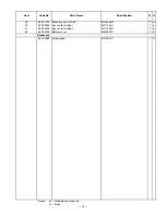
Page 20: ...Black key set LSK 5P M140369 2 1 A 20 6922 3990 Key contact rubber M111764 1 1 A 21 6922 4000 Key contact rubber M111765 1 1 A 22 6925 2160 Battery cover M340490 1 1 B Accessory 6916 7880 Music stand...

Page 21: ...MA0800761A Aug 1996...
Reviews: