3
— 46 —
No
Operation
Display
Inspection contents
1
2
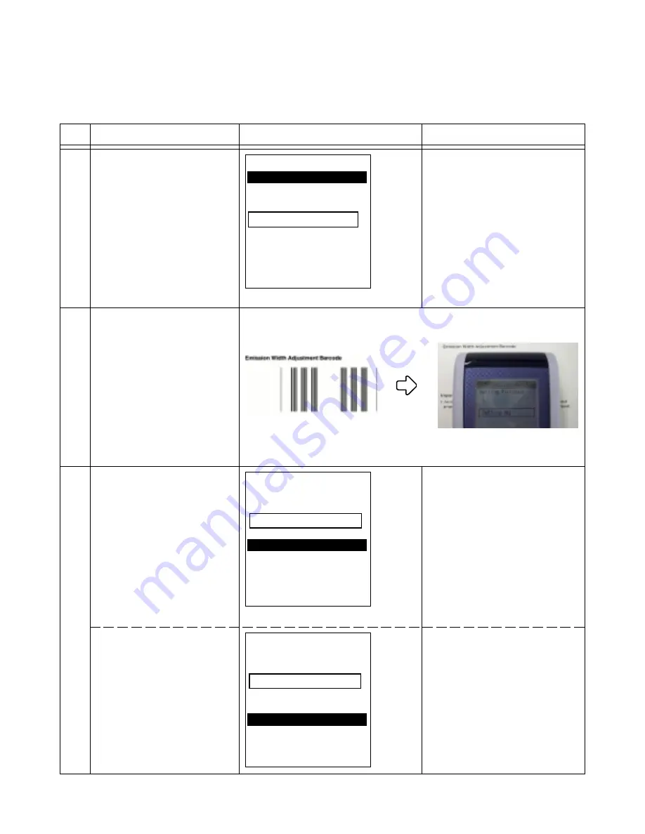
Display "Test Menu #3".
Select "5.OBR Set".
Place DT-X5 on "Emission
Width Adjustment Barcode"
Note: The barcode is in the
"Adjusting Laser Emission
Width" of the User’s Guide.
Laser light turns on and automati-
cally performs adjustment.
Confirm the display changes to
"Setting OK" as shown in the left
after about 1 second.
Push "ENT" key.
(When an error occurs)
Confirm the display on the left.
OBR Setting Ver1.00
1.OBR Calib SET
Setting Status
Setting NG
9.EXIT
OBR Setting Ver1.00
Setting Finished
Setting OK
1.SET
2.Retry
9.CANCEL
OBR Setting Ver1.00
Setting Finished
Setting OK
1.SET
2.Retry
9.CANCEL
4-5. OBR CalibrationSetting
Perform the OBR Calibration Setting after replacing the following;
•
Laser module
•
Main PCB assy
When the setting is incorrect, the
display changes to "Setting NG"
as shown in the left.
Push "2" key in this case and try
again.
Summary of Contents for DT-X5M10E
Page 1: ...SERVICE MANUAL DT X5M10E M10R PX 791EE 791ME JUN 2004 HANDHELD TERMINAL Ver 1 Nov 2004 ...
Page 69: ... 67 6 EXPLODED VIEW FRONT CASE ASSY 3 1 7 4 2 5 6 ...
Page 70: ... 68 MIDDLE CASE ASSY 9 8 11 12 See LCD BLOCK DT X5M10R only See LASER BLOCK 14 13 15 10 14 ...
Page 72: ... 70 LCD BLOCK 43 42 41 38 39 40 36 37 35 LASER BLOCK ...


