background image

FX-9700GE

 (LX-370)

MAR. 1994

R

(without price)

INDEX

Summary of Contents for FX-9700GE

Page 1: ...FX 9700GE LX 370 MAR 1994 R without price INDEX...

Page 2: ...4 4 DATA TRANSFER CHECK 8 5 DATA COMMUNICATIONS 5 1 Connecting Two fx 9700GE Units 9 5 2 Before Starting Data Communications 9 5 3 Setting Communications Parameters 10 5 4 Using ALL Range and Factor 1...

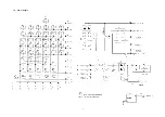
Page 3: ...1 1 SCHEMATIC DIAGRAM 1 1 Main PCB...

Page 4: ...2 1 2 Power Supply...

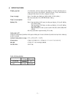
Page 5: ...inuous display of 0 with battery type LR03 AM4 Approximately 350 hours continuous display of 0 with battery type R03 UM 4 Approximately 2 years power switch off with LR03 AM4 R03 UM 4 Memory protectio...

Page 6: ...FT AC 4 5 F6 ab c AC Press the above key at the same time 1 6 No Display Lx370 TEST MODE 1 LCD 2 KEY 3 RAM 4 DET 5 TRS 0 Rst RUN COMP G type RECT CONNECT angle Deg display Norm 1 M D Cpy M Disp ZOOM P...

Page 7: ...5 NO OPERATION DISPLAY NOTE 7 8 EXE EXE 9 10 11 12 No Display FRAME Display 1 EXE EXE EXE ALL DOT Display CHECKER Display REVERSE CHECKER Display Lx370 TEST MODE 1 LCD 2 KEY 3 RAM 4 DET 5 TRS 0 Rst...

Page 8: ...370 TEST MODE 1 LCD 2 KEY 3 RAM 4 DET 5 TRS 0 Rst Trace ZOOM 3 Lx370 TEST MODE 1 LCD 2 KEY 3 RAM 4 DET 5 TRS 0 Rst RAMSIZE 32K bytes Press each key sequentially as it appears on the display RAMSIZE 32...

Page 9: ...7 NO OPERATION DISPLAY NOTE 18 19 F1 SHIFT AC 20 0 No Display RESET RESET ALL MEMORIES RESET ALL YES NO RESET ALL MEMORIES...

Page 10: ...5 Slave 2 Master 1 Lx370 TEST 1 TEST MODE 2 Transmit 3 Exit Lx370 TEST MODE 1 LCD 2 KEY 3 RAM 4 DET 5 TRS 0 Rst TRANSMIT Check 1 COM Check 2 RANDOM Data Out 0 Self 1 Send 2 Receive COM END WAITING CO...

Page 11: ...nector covers in a safe place so you can replace them after you finish your program communications 3 Connect the two units using the SB 62 cable Important Keep the connectors of the fx 9700GE covered...

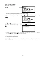
Page 12: ...s more below About the Data Type Selection Screen Whenever you press F1 TRN to send data or F2 RCV to receive data a data type selection screen appears on the display Send Unit Receive Unit F1 TRN F2...

Page 13: ...ter setting procedure and return the settings to what they were before you changed them press AC before pressing EXE to store the parameters 5 4 Using ALL Range and Factor The following procedures sho...

Page 14: ...he send operation is complete Press AC to return to the LINK Mode Receive Unit Starting from the LINK Mode press the function key to enter the receive mode F2 RCV Make sure that the pointer is located...

Page 15: ...s happens press AC to clear the error A TRANSMIT ERROR or RECEIVE ERROR occurs during data communications if the cable becomes disconnected if the parameters of the two units do not match or if any ot...

Page 16: ...r contact on power switch Poor connection on PC joiner Poor soldering on LSI capacitor or resistor Weak battery Dirt or poor contact on battery Poor contact on power switch Poor connection on PC joine...

Page 17: ...15 7 DISASSEMBLY VIEW 6 7 9 0 8 4 1 3 A 5 2 B T O...

Page 18: ...16 LOCK CR2032 KL GH P N QR LOCK CR2032 CD IJ EF M S B R...

Page 19: ...17 B B A A B B A A UV j W k XY fg no k p lm hi de bc Z a...

Page 20: ...18 st qr wx uv...

Page 21: ...19 y z...

Page 22: ...C N 24 6407 9910 Battery cover L370 A211188 1 1 1 20 C N 25 6408 0050 Display plate L370 A312942 1 1 1 1 C N 26 6408 0060 Battery holder L370 A312944 1 1 1 20 C N 27 6408 0200 Label L370 A413640 1 1 0...

Page 23: ...0 Tape A L370AAQ A413596 2 0 2 20 X 72 6403 9331 Tape C L170 A413108A 1 2 2 10 X N 73 6407 9930 Flat screw A L370 A310044 41 1 0 50 C 74 6334 7860 Flat screw A G361 A33953 13 0 1 50 C N 75 6408 0190 T...

Page 24: ...012010 1 1 5 X N 2805 8700 Electrolytic capacitor ECE A1AKA220I 1 1 20 C 2101 0952 MOS IC TC4049BF TP1 1 1 1 C N 2105 3206 MOS IC RH5VL40CA T1 1 1 10 C 2259 0959 Chip digital transistor DTC114YKT 146...

Page 25: ...8 11 10 Nishi Shinjuku Shinjuku ku Tokyo 160 Japan Telephone 03 3347 4926...

Reviews: