background image

– 43 –

IT-9000

[4] Audio (Rec & Rep)

No

Operation/Test Details

1

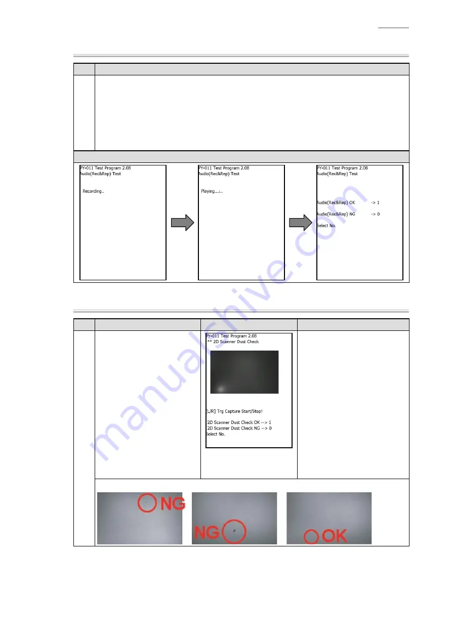
Select “[4].Audio(Rec&Rep)” from MENU-3 screen.
As recording stats, talk over the microphone of IT-9000. Recorded sound is played back and 
output from the speaker.
Then, the manual judgment screen appears.

If sound is output (OK):

 Press the “1” key to return to the menu screen.

If sound is not output correctly (Failure):

 Press the “0” key to return to the menu screen.

Display

[8] 2D Scanner Dust Check (2D type only)

No.

Operation

Display

Test Details

1

Select “[8] 2D Scanner Dust 
Check” from MENU-3 screen.

Take a picture of white paper 
without taint by pressing the 
“Trigger” key.

Check if any foreign substances 
are included in the captured 
image.
The manual judgment screen 
appears. 

If nothing is found or the 
included substance is small 
(OK):

Press the “1” key to return to 
the menu screen.

If the substance is large 
(Failure):

Press the “0” key to return to 
the menu screen.

<Criteria for determining>

Summary of Contents for IT-9000 Series

Page 1: ...SERVICE MANUAL HANDHELD TERMINAL IT 9000 MAR 2012 Ver 8 Mar 2018...

Page 2: ...es of merchantability or tness for any particular purpose 2012 CASIO Computer Co Ltd All rights reserved The BLUETOOTH registered trademark is owned by Bluetooth SIG Inc U S A and licensed to CASIO Co...

Page 3: ...t Procedure 21 4 2 Performing a Full Reset Initialization 21 5 HARDWARE TEST SETTING 22 5 1 General 22 5 2 Initial Settings 23 5 3 Function Test 27 6 DISASSEMBLY AND REASSEMBLY 67 6 1 Precautions befo...

Page 4: ...ates something you should not do The symbol shown here indicates you should not try to take the unit apart A black circle indicates something you should do The symbol shown here indicates you should u...

Page 5: ...the Handheld Printer Terminal s reader port and the operator body This Handheld Printer Terminal must not be co located or operating in conjunction with other transmitter Foreign Objects Take care to...

Page 6: ...mpact Never pierce the battery pack with nails hit it with a hammer or step on it Use only the speci ed battery charger to charge the battery pack Never place the battery pack in a microwave oven or a...

Page 7: ...r a long period The housing of the AC adaptor can become warm during normal use At least once a year unplug the AC adaptor from the wall outlet and clean any dust that builds up between the prongs of...

Page 8: ...0E CE 1 LED 11b g 82 55mm 2 1 Microsoft Windows Embedded CE 6 0 R3 2 Microsoft Windows Mobile 6 5 Professional 3 Microsoft Windows Mobile 6 5 Classic 4 58 mm roll paper size is available Y Model B Pro...

Page 9: ...82 55mm 2 IT 9000 GM30E C CE 1 LED 11b g n 82 55mm 2 1 Microsoft Windows Embedded CE 6 0 R3 2 Microsoft Windows Embedded Handheld 6 5 Professional 3 Microsoft Windows Embedded Handheld 6 5 Classic 4 5...

Page 10: ...daptor without AC CORD AD S42120C N5 AC Adaptor without AC CORD HA G20BAT Battery Pack AC CORD EU Power Cord for Europe AC CORD US Power Cord for North America AC CORD TW Power Cord for Taiwan AC CORD...

Page 11: ...tion 0 38 mm 410 mm Resolution 1 0 mm 2D Stacked 65 mm Resolution 0 254 mm 260 mm Resolution 0 5 mm 2D Matrix 55 mm Resolution 0 38 mm 195 mm Resolution 0 5 mm The value varies with an environment of...

Page 12: ...BPSK QPSK CCK 16QAM 64QAM ITU code Emission Identi er 802 11b D1D G1D 802 11g G1D Radio Frequency 802 11b 2 400 2 497 GHz 802 11g 2 400 2 4835 GHz Transmission Rate 802 11b Max 11 Mbps 802 11g Max 54...

Page 13: ...varies with an environment of usage kinds of codes and printing status Scan Width Max 40 mm Depth 48 mm Max 275 mm Depth 400 mm The value varies with an environment of usage kinds of codes and printi...

Page 14: ...l Interval 5 MHz Channel Bandwidth 20 MHz Output 802 11b Min 11 0 dBm Max 17 0 dBm 802 11g Min 9 0 dBm Max 15 0 dBm 802 11n TBD Other Function Roaming among multiple access points Depends on access po...

Page 15: ...on is required Once paper width is changed to 58 mm 80 82 55 mm width paper cannot be used unless the paper width is properly changed by software Print width 72 mm for 80 mm 82 55 mm width paper 48 mm...

Page 16: ...925 960 MHz GSM1800 DCS1800 Uplink 1710 1785 MHz Downlink 1805 1880 MHz GSM1900 PCS1900 Uplink 1850 1910 MHz Downlink 1930 1990 MHz No of Channels GSM850 124 GSM900 174 GSM1800 DCS1800 374 GSM1900 DCS...

Page 17: ...D G25E D GC25E D GMC30E D GM30E D Band I 299 Band II 299 Band V 124 Band VI 49 Band VIII 174 IT 9000 G05E B GE B GMC25E B GMC30E B G25E B G20E B GC25E B GM30E B IT 9000 G05E C GE C GMC25E C GMC30E C...

Page 18: ...mm Readable Area 40mm 20mm Depends on the kinds of cards and tags Communication Protocol Standards Supported Operation check con rmed IC ISO14443 Type A MIFARE Standard MIFARE Ultralight ISO14443 Type...

Page 19: ...rox 2 Megapixels 1 600 x 1 200 pixel Imaging Element 1 4 0 type CMOS F Value 2 8 5 Focusing f 3 45 mm Auto focus Focus Range 10 cm in nite LED Flash 21 000 mcd In steady lighting state Speaker Warning...

Page 20: ...Backup battery is fully charged Normal temperature Backup Time Main Battery Backup Battery RAM Approx 72 hours After a main battery remaining alarm occurs Main Battery Charge Time Approx 5 hours Norma...

Page 21: ...4 IT 9000 2 2 Part Names and Functions NOTE External form varies with models Left Front Right Top Bottom Back 17 17 16 12 13 10 1 2 3 7 8 4 5 6 9 10 14 11 15 18 19 19 27 21 24 22 23 20 26 28 25 19 25...

Page 22: ...1 R Program Trigger Key Used to perform barcode reading 12 L Program Trigger Key Used to perform barcode reading 13 SD Card Slot Used to insert a SD card 14 DC Jack Connect an AC adaptor 15 USB Port C...

Page 23: ...rsor 4 ENT Enter Key Used to enter the input value 5 Used to input a period 6 Numeric Keys Used to enter numeric values and letters 7 dash 8 Right cursor Key Used to move the cursor to the right 9 Lef...

Page 24: ...GMC25E B IT 9000 GMC25E C IT 9000 GMC25E D IT 9000 20E Approx 112 255 66 mm Approx 600 g IT 9000 25E IT 9000 25E B IT 9000 25E C IT 9000 G20E Approx 112 255 66 mm Approx 625 g IT 9000 G20E B IT 9000 G...

Page 25: ...g parts 2 Including battery pack but excluding roll paper 2 4 Environmental Performance Item Speci cations Remarks Temperature In operation 20 C 50 C 0 40 C during charging Printing quality guaranty r...

Page 26: ...IC1 CPU ROM RAM FPC KEY SIM Card Slot SAM Card Slot SAM Card Slot FPC MCR MCR Module PCB Side MCR Module Head Side FPC SUP GND SAM Controller SAM Controller SAM Controller Battery Cover Detection Swit...

Page 27: ...one Network USB Client USB Client USB Host USB Host LAN Port Battery Pack HA G20BAT SAM Card SAM Card SIM SAM Card SD Card AC Adaptor AD S42120B C Car Mounted type Battery Charger HA L35CHG Car adapto...

Page 28: ...the following conditions exists When you want to delete installed programs and settings and resume the terminal to the initial condition When you are no longer able to use the Handheld Printer Termin...

Page 29: ...ain the test program Diag_It9000 zip Download from website Unzip Diag_It9000 zip and copy it to a SD card For both test object IT 9000 and opponent IT 9000 Install the SD card Copy the test program fr...

Page 30: ...stall the initial setting program and data is the same as that for installing the test program and test data For details refer to 5 3 3 Installing the Test Program and Test Data 5 2 2 Setting Procedur...

Page 31: ...cing the WAN GPS MODULE with a new one be sure to perform the following procedure NOTE If the remaining battery level is 40 or less do this procedure while supplying power from the AC adaptor Otherwis...

Page 32: ...o perform the following procedure No Operation Display Test Details 1 Start up WANModuleSetting exe under My Device FlashDisk DIAG The screen on the right appears Tap OK to reset IT 9000 once 2 After...

Page 33: ...irm exe under My Device FlashDisk DIAG NFCFirmTool The current version and a new version for upgrading appear NOTE In the case shown on the left both versions are the same as the upgrading has been do...

Page 34: ...n 5 LCD Backlight Calibration B Common Luminance meter 6 Operation Charge LED B Common 8 Speaker A Common 9 Key Backlight A Common ALL TEST MENU 3 1 LED Flash A Camera 3 Low Voltage Detection B Common...

Page 35: ...ltmeter DC ammeter 4 Splash Cover A Common 5 MCR Read A MCR Magnetic card for testing Special Test tests without using the test program Image Scanner Demo A 2D W LAN A Common W LAN access point W LAN...

Page 36: ...ive test items RFID tag 85 54 mm Test Object External expansion I F test PCB USB cradle USB cable for host AC adaptor AC cord DC power supply unit Output 00 10 V 3 A DC ammeter Range 10 mA 100 mA 1 A...

Page 37: ...n your PC 3 Copy the unzipped data to the root directory of SD card as shown below SetFactoryTool exe readMe txt DIAG Folder ActiveSync Shortcut BTLineTest Shortcut CF Power Shortcut CradleUSBTest Sho...

Page 38: ...ection checkbox is automatically set to OFF and USB communication between the test PC via ActiveSync Windows Mobile Device Center is impossible To establish USB communication via ActiveSync Windows Mo...

Page 39: ...splays all test items Displays test item limited to model Do not select Do not used PY 011 Test Program Ver x xx Top MENU 1 All Test 2 Test limited to model Auto judge 3 Pattern Test Log 4 Assembly Te...

Page 40: ...nt Printer 4 Splash Cover 5 MCR Read 6 Bluetooth I F Previous Menu CLR Exit PY 011 Test Program Ver x xx All Test MENU 3 1 LED Flash 2 LED Flash Calibration 3 Low Voltage Detection 4 Audio Rec Rep 8 2...

Page 41: ...The screen returns to the menu screen If any problem The failed addresses correct data and wrong data are displayed Press the ENT key to return to the menu screen 2 ROM No Operation Display Test Deta...

Page 42: ...y to return to the menu screen 4 Key 1 No Operation Display Test Details 1 Select 4 Key 1 from MENU 1 screen The key statuses are displayed The pressed key appears inverted on the screen Press all key...

Page 43: ...rror indication is displayed Press the ENT key to return to the menu screen 2 When the screen on the right appears return the battery pack cover lock switch to position LOCK and press the ENT key Auto...

Page 44: ...EEIFtest txt empty le and store it in the directory of a USB memory 2 Connect the USB memory to the USB port of the external expansion I F test PCB 3 Undo one screw and remove the extension port cover...

Page 45: ...ENT key changes the pattern screens in sequence After 8 pattern screens have been displayed manual judgment screen is displayed If the patterns are displayed correctly Press the 1 key to return to th...

Page 46: ...n No Operation Display Test Details 1 Select 5 LCD Backlight Calibration from MENU 2 screen A number located below 5 is displayed in blue Set a luminance meter onto the LCD of IT 9000 Then press the n...

Page 47: ...display pattern of the LCD successively change as follows After 5 kinds of lighting and display patterns have appeared the manual judgment screen is displayed If lighting and display are correct OK Pr...

Page 48: ...lso repeated two times Then the manual judgment screen appears If each tone is emitted correctly OK Press the 1 key to return to the menu screen If each tone is not emitted correctly Failure Press the...

Page 49: ...C power supply at a minimum position and then turn ON its power DC power supply unit DC voltmeter Diode IF 3 0 A Max Turn the right lock switch for the battery pack cover to the LOCK position No Opera...

Page 50: ...Press the 0 key to return to the menu screen Display 8 2D Scanner Dust Check 2D type only No Operation Display Test Details 1 Select 8 2D Scanner Dust Check from MENU 3 screen Take a picture of white...

Page 51: ...mera from MENU 3 screen Capturing image is displayed on the preview screen Also the manual judgment conditions are displayed If displayed properly OK Press the 1 key to return to the menu screen If no...

Page 52: ...s not set to the write protect position and then insert the SD card into the SD card slot of IT 9000 No Operation Display Test Details 1 Select 4 SD Card from MENU 4 screen A test data is written read...

Page 53: ...5 V Backup battery MUX2 Between 2 7 to 3 6 V W LAN temperature MUX4 Between 0 to 85 C CPU temperature MUX5 Between 0 to 85 C LED temperature MUX6 Between 0 to 85 C Print head voltage MUX0 Between 6 5...

Page 54: ...n If any problem An error indication is displayed Failure Press the ENT key to return to the menu screen 3 SD Card 2 2nd SD type NOTE Be sure that the lock switch of the SD card is not set to the writ...

Page 55: ...n is displayed Press the ENT key to return to the menu screen 6 SD Write Protect NOTE Be sure that the lock switch of the SD card is not set to the write protect position and then insert the SD card i...

Page 56: ...urrent Sleep Mode from MENU 6 screen Automatically judges if the current value is within 30 to 110 mA For Model C 110 mA or less If OK The screen returns to the menu screen If out of range Failure An...

Page 57: ...s 1 Select 7 Current W LAN from MENU 6 screen Automatically judges if the current value is within 150 to 250 mA If OK The screen returns to the menu screen If out of range Failure An error indication...

Page 58: ...y checks the NFC rmware version and judges if a combination of the NFC rmware and the NFC ASSY is correct When the check result is OK automatically starts to access to the RFID tag Access UID Read Dat...

Page 59: ...o Operation Display Test Details 1 Select 8 SD2 Write Protect from MENU 7 screen When the screen on the right appears remove the SD card and press the ENT key Write protect signal becomes invalid 2 Au...

Page 60: ...The number of SAM cord slots di ers depending on the models SAM SAM SAM No Operation Display Test Details 1 Select 9 SAM Read from MENU 7 screen Communicates with the SAM cards and automatically judge...

Page 61: ...elect 2 Printer all check from MENU 8 screen Automatically detects the markers and barcodes Then upon detection printing starts Visually check the quality of printed patterns on the roll paper The man...

Page 62: ...Turn the right lock switch for the battery pack cover to the LOCK position DC ammeter No Operation Display Test Details 1 Adjust the DC power supply output so that the DC voltmeter reads 7 4 V and the...

Page 63: ...o NORMAL After con rming the display NORMAL close the splash cover 2 After con rming that the cover close status is detected open the splash cover Detects open close of the splash cover and automatica...

Page 64: ...ration Display Test Details 1 Select 5 MCR Read from MENU 8 screen Set the magnetic card for testing to the card reader and slide it at a constant speed Automatically judges the read out results after...

Page 65: ...to close the screen Perform the test for all menus Scan barcode Scan several barcodes Scan target barcode Challenge scanning speed and Setting For other than Capture image the decode message etc are...

Page 66: ...ettings tab Then input SSID IP address etc of the target access point 3 Select Start NetSearch in that order Tap Tools and then select Ping or Signal Carry out wireless test using Ping and Signal func...

Page 67: ...ipt les Make les referring to the following format and save them to the folder C Program Files LMWIN on your PC SO C USBDATA DAT C FlasdDisk DIAG WLAN RO C FlashDisk DIAG WLAN USBDATA DAT C Store USBD...

Page 68: ...g to the following format and save them to the folder C Program Files LMWIN on your PC SO C USB2DATA DAT C FlasdDisk DIAG WLAN RO C FlashDisk DIAG WLAN USB2DATA DAT C Store USB2DATA DAT on the C drive...

Page 69: ...rt up BTServer exe under My Device FlashDisk DIAG WLAN Select one from Line A to H 2 Test object IT 9000 Start up BTLineTest exe under My Device FlashDisk DIAG WLAN From Line A to H select the same on...

Page 70: ...n the same way 6 WAN WAN type only NOTE Insert the SIM card for testing into the SIM card slot before starting test SAM SIM SAM Preparation No Operation Display Test Details 1 Select Start Settings Co...

Page 71: ...ation tab Check if information on WAN and SIM card is displayed 2 Select Status tab Check if electric wave receiving signal strength is displayed in RSSI Checking by telephone communication No Operati...

Page 72: ...starting test SAM SIM SAM Preparation No Operation Display Test Details 1 Select Start Settings Connections WAN Settings in that order In the WAN Setting screen select Power tab Check WAN Power and t...

Page 73: ...or positioning is not possible is shown Received Display the time set by the signal received satellite S N Radio The satellite number is shown on the left while on the right the intensity of that sat...

Page 74: ...antenna cable disconnect and connect it horizontally After connecting be sure that it is securely connected to the socket Adhesive tape is not reusable Use the new one Tool list The following tools ar...

Page 75: ...MCR type models undo 8 screws S2 MCR model 3 Remove the L CASE UNIT L CASE ASSY NOTE For MCR type models also remove the MCR CASE ASSY L CASE UNIT L CASE ASSY MCR CASE ASSY Notes on reassembling Befor...

Page 76: ...2D Only CAM BLIND and CAMBLIND TAPE NOTE For models with camera stick the CAM FILTER EXT COVER and EXT CUSHION SDIO COVER and SDIO CUSHION VIBRATOR MOTOR L CASE ASSY Only Screw S5 SDIO COVER SDIO CUSH...

Page 77: ...na 2 Disconnect the connectors 3 places NOTE As the lead wires of the Trigger switch are thin handle them carefully 3 Release the connector lock and disconnect the FPCs 4 places 4 Disconnect the W LAN...

Page 78: ...s 1 Pass 2 FPCs through the slit NOTE To make it easier use tweezers FPC Touch Panel FPC KEY UNIT Pass 2 FPCs through the slit in the I CASE 2 Assemble the I CASE UNIT while con rming that no calbes a...

Page 79: ...he 2D FPC to the side of the CAM HOLDER with double sided tape and then pass the 2D FPC through the guide 4 Pass the 2D FPC thoght the core NOTE The core is stick to the I2 CASE with double sided tape...

Page 80: ...73 IT 9000 Notes on reassembling For the camera equipped model Model C attach the tape Sheet Core...

Page 81: ...NCAP UNIT NOTE For non WAN type models remove the SBAT HOLDER SBAT HOLDER 5 Undo 6 screws S12 6 Remove the CAPACITOR NOTE It is stuck with double sided tape 7 Remove the I2 CASE ASSY CAPACITOR CN SUB...

Page 82: ...E CAP TAPE 2 Stick the EXT SPACER SBAT D TAPE EXT SPACER CAP TAPE 3 SHIELD TAPE 1 Stick the SHIELD TAPE by aligning it with the positioning pins 2 Fold the SHIELD TAPE along the red dotted lines and s...

Page 83: ...the connector lock and remove the FPC 1 place 2 Remove the LCD UNIT NOTE The COIL SPRINGs 3 places can come o In this case do not lose them FPC LCD CN BAT UNIT Double sided tape Screws S3 BAT UNIT LC...

Page 84: ...ove the FPC 1 place 2 Remove the CAM HOLDER 3 Remove the CAMERA ASSY Notes on reassembling When replacing the CAM HOLDER stick double sided tape as shown 6 3 5 SUB UNIT non WAN GPS type 1 Disconnect t...

Page 85: ...IT and disconnect the connector 1 place GPS CABLE Screws S3 CN SUB UNIT LNA UNIT Notes on reassembling 1 Connect the cable to the LNA UNIT 2 Turn the LNA UNIT by 180 degrees to twist its cable and the...

Page 86: ...79 IT 9000 4 Undo 7 screws S3 S10 and S13 5 The following parts can be disassembled Screws S10 Screws S3 Screws S13 WAN ANTENNA WAN GPS MODULE W LAN ANTENNA SUB UNIT SUB FPC UNIT WAN CN PLATE GPS CABL...

Page 87: ...PS MODULE Model Type MC8795V Model A MC8092 Model B Model C MC8795V Antenna Cable GPS CABLE MC8092 Since the MC8092 module has three identical connectors connect the following two cables Main Connecto...

Page 88: ...2 Release the connector lock and disconnect the FPC 1 place 3 Remove the MAIN UNIT MAIN UNIT Notes on reassembling Insert the MAIN UNIT into the under part of the cut ribs 2 places 6 3 8 PRINTER 1 Un...

Page 89: ...82 mm Printer Attach the SPACER PRINTER for the 80 mm Printer SPACER PRINTER When the I CASE SUBASSY is replaced with a new one attach the following parts to the replaced one B PLATE TAPE SHD PR B BO...

Page 90: ...PEINTER CUTTER ASSY PW UNIT 1 Remove the SCREW PROTECT 2 Undo 4 screws S8 3 Remove the PW UNIT and PW SUBASSY NOTE The speaker is stuck with double sided tape KEY UNIT 1 Undo 4 screws S8 2 Remove the...

Page 91: ...NIT 3 Remove the TR SUBASSY NOTE The TR SUBASSY is stuck with double sided tape TR PLATE TR UNIT TR L SUBASSY TR R SUBASSY 6 4 4 NFC ASSY 1 Release the connector lock and disconnect the FPCs 2 places...

Page 92: ...85 IT 9000 6 4 5 NFC ANT ASSY 2D ASSY 1 Undo 2 screws S3 and remove the NFC ANT ASSY 2 Undo 3 screws S3 and remove the 2D ASSY 2D ASSY Screws S3 NFC ANT ASSY Screws S3 2D PLATE 2D ASSY NFC ANT ASSY...

Page 93: ...he MCR U2 CASE 3 Disconnect the connector 1 place Screws S7 Screws S3 Connector MCR U2 CASE 4 Undo 2 screws S7 5 Remove the MCR NOTE The cable is stuck with double sided tape NOTE After removing the M...

Page 94: ...connector lock and disconnect the FPC 1 place Screw S3 MCR PCB HOLDER FPC MCR MCR Notes on reassembling When replacing the MCR perform the following procedure 1 Assemble the SPACER MCR on the MCR 2 S...

Page 95: ...part of the clear plate 4 Peel o the release paper from double sided tape MCR TAPE and then pass the MCR cable through the hole NOTE Assemble the MCR so that its cable does not run the area shown by...

Page 96: ...2 7 2 3 Model C 108 7 2 4 Model D 114 7 3 EXPLODED VIEW HA L60IO L62IO L30CHG L35CHG 119 7 4 PARTS LIST HA L60IO L62IO L30CHG L35CHG 120 Notes 1 The numbers in the item column correspond to the same n...

Page 97: ...NNER CASE 7 1 5 LOWR CASE 2 PR COVER UNIT 108 10 Tape WLAN Antenna 11 GPS Cable 16 NFC Cable 111 Sheet Model C CAMERA type 18 Tape NFC Cables 21 22 19 Ferrite Core 2D Cable 20 Double sided tape Ferrit...

Page 98: ...E S9 26 3 26 6 26 4 26 5 26 2 26 7 26 1 27 33 39 38 32 43 36 35 34 S9 26 35 36 29 30 31 37 41 40 28 42 S3 S3 S7 S8 S8 54 Tape 2D Cable 55 S8 48 Tape Connector 49 52 MCR type 45 50 51 47 53 5 S3 S3 S3...

Page 99: ...es 89 Tape Connector 69 68 57 65 56 63 72 77 77 75 78 75 76 76 79 85 83 S3 S3 S13 87 1 S3 81 84 82 80 87 88 90 90 74 73 70 62 64 58 71 59 60 S11 S9 66 61 S3 67 WAN type WAN type OTHER type 2nd SD type...

Page 100: ...93 IT 9000 7 1 4 I2 INNER CASE A B A B Gasket 97 Double sided tape 96 91 98 92 93 99 97 100 95 S3 94 100...

Page 101: ...94 IT 9000 7 1 5 LOWER CASE 1 LOWER CASE UNIT Model A LOWER CASE ASSY Model A Model B Model C Model D 1 2 1 3 1 5 1 4 1 6 S6 S6 1 1 LOWER CASE UNIT 110 LOWR CASE ASSY...

Page 102: ...95 IT 9000 7 1 6 BUNDLED ITEMS 80 mm Paper Width Adjuster 101 58 mm Paper Width Adjuster 102 Neck Strap 103 Stylus Holder 104 Neck Strap Rings 105 Stylus 106 Hand Strap 107...

Page 103: ...Y BATTERY RJC506166 001 TK 1 1 1 1 1 1 1 1 1 1 1 1 1 1 1 C 4 10426851 COVER ASSY SIM RJC506382 001 TK 1 1 1 1 1 1 1 1 1 1 1 1 1 1 1 C 5 10426850 CASE ASSY MCR RJC506283 001 TK 1 1 1 1 1 C 5 1 10473661...

Page 104: ...6084 LABEL RATING RJC505951 022V01 1 X 21 10426081 LABEL RATING RJC505951 019V01 1 X 21 10426082 LABEL RATING RJC505951 020V01 1 X 21 10426083 LABEL RATING RJC505951 021V01 1 X 23 10239292 LABEL REVIS...

Page 105: ...NTENNA ASSY NFC RJC506437 001 TK 1 1 1 1 C 28 10430100 ANTENNA ASSY NFC RJC506437 002 TK 1 1 1 1 1 1 1 1 1 1 1 C 29 10415519 SUBASSY PW RJC505871 001V01 1 1 1 1 1 1 1 1 1 1 1 1 1 1 1 B 30 10428871 SPA...

Page 106: ...1 1 1 1 1 1 X 59 10415614 STP PLATE BATTERY RJC506262 001V01 1 1 1 1 1 1 1 1 1 1 1 1 1 1 1 X 60 10422018 STP SHEET BATTERY RJC506343 001V01 1 1 1 1 1 1 1 1 1 1 1 1 1 1 1 X 61 10422025 SHEET A B BOX R...

Page 107: ...SBAT RJC506277 001V01 1 1 1 1 1 1 X 89 10288956 TAPE CONNECTOR B RJC503687 002V01 2 2 2 2 2 2 2 2 2 2 2 2 2 2 2 X 90 10303503 TAPE DOUBLE GPS ANT RJC503863 001V01 1 1 1 1 1 1 1 1 1 1 1 1 1 1 1 X S3 10...

Page 108: ...102 10415604 58 mm Paper Width Adjuster RJC506183 001V01 1 1 1 1 1 1 1 1 1 1 1 1 X 10³ 10365029 Neck Strap RJC504881 001V01 1 1 1 1 1 1 1 1 1 1 1 1 1 1 1 X 10⁴ 10169710 Stylus Holder RJC501565 001V02...

Page 109: ...B 3 10426848 COVER ASSY BATTERY RJC506166 001 TK 1 1 1 1 1 1 1 1 1 1 1 C 4 10426851 COVER ASSY SIM RJC506382 001 TK 1 1 1 1 1 1 1 1 1 1 1 C 5 10426850 CASE ASSY MCR RJC506283 001 TK 1 1 1 C 5 1 104736...

Page 110: ...1GFM RJC505951 041V01 1 X 21 10494214 RATING PY011LF RJC505951 042V01 1 X 21 10494216 RATING PY011DF RJC505951 043V01 1 X 23 10239292 LABEL REVISION RJC502719 001V01 1 1 1 1 1 1 1 1 1 1 1 X 24 1049983...

Page 111: ...1 1 1 1 1 1 1 1 1 1 1 X S9 10422030 SCREW S BDMA 2X4B3ME 2 2 2 2 2 2 2 2 2 2 2 X 27 10430097 NFC ASSY RJC506185 001 TK 1 1 1 1 B 27 10430098 NFC ASSY RJC506185 002 TK 1 1 1 1 1 1 1 B 28 10430099 ANTEN...

Page 112: ...RJC502686 001V01 10 10 10 10 10 10 10 10 10 10 10 X INNER CASE ASSY 56 10415616 CASE SUBASSY INNER RJC506264 001V01 1 1 1 1 1 1 1 1 1 C 56 10426086 CASE SUBASSY INNER RJC506264 002V01 1 1 C 57 104286...

Page 113: ...79 10415512 WAN ANTENNA FILMANT GSM PY11 1 1 1 1 1 1 1 1 X 80 10494584 WAN GPS MODULE MC8092 SKU 1101501 1 1 1 1 1 1 1 1 B 81 10422023 INS SHEET WAN RJC506353 001V01 1 1 1 1 1 1 1 1 X 82 10415655 GPS...

Page 114: ...3 3 3 3 3 3 3 3 3 3 3 X 98 10415646 SPACER EXT RJC506271 001V01 1 1 1 1 1 1 1 1 1 1 1 X 99 10428654 TAPE SHIELD RJC506459 001V01 1 1 1 1 1 1 1 1 1 1 1 X 100 10428658 GASKET RJC506493 001V01 2 2 2 2 2...

Page 115: ...1 COVER ASSY SIM 1 1 1 1 1 1 1 1 1 1 1 1 C 5 10426850 CASE ASSY MCR 1 1 1 1 C 5 1 10473661 MCR SPACER IT 9000 2 2 2 2 C N 6 10528861 FILTER 2D RJC505922 004 TK RJC506166 001 TK 1 RJC506382 001 TK 1 RJ...

Page 116: ...1 RJC505951 069V01 RJC505951 070V01 1 X 23 10239292 LABEL REVISION RJC502719 001V01 1 1 1 1 1 1 1 1 1 1 1 1 1 X 1 1 X 1 1 X 24 10422019 LABEL CAUTION PRINTER RJC506347 001V01 24 10426557 LABEL CAUTION...

Page 117: ...Y NFC 28 10430100 ANTENNA ASSY NFC 29 10415519 SUBASSY PW 1 1 1 1 1 1 1 1 1 1 1 1 B N 31 10528726 PW UNIT 1 1 1 1 1 1 1 1 1 1 1 1 B 1 1 1 1 1 1 1 1 1 1 1 1 X 1 1 1 1 1 1 1 1 1 1 1 1 C 1 1 1 1 1 1 1 1...

Page 118: ...3 3 3 3 3 3 X 56 10415616 CASE SUBASSY INNER 56 10426086 CASE SUBASSY INNER 57 10428657 SPACER PRINTER 58 10415606 STOPPER BATTERY 59 10415614 STP PLATE BATTERY 60 10422018 STP SHEET BATTERY 61 104220...

Page 119: ...ER CAM 87 1 10430102 CAMERA ASSY 1 1 1 1 1 B 1 1 1 1 X 2 3 3 3 3 2 3 3 3 3 2 2 X 1 1 1 1 1 1 1 1 1 1 1 1 X 9 6 6 6 6 9 6 6 6 6 9 9 X 88 10415623 HOLDER SBAT 89 10288956 TAPE CONNECTOR B 90 10303503 TA...

Page 120: ...juster RJC506183 001V01 1 1 1 1 1 1 1 1 1 1 1 X 1 1 1 1 1 1 1 1 1 1 1 1 X 1 1 1 1 1 1 1 1 1 1 1 1 X 10³ 10365029 Neck Strap 104 10169710 Stylus Holder 105 10250686 Neck Strap Rings RJC504881 001V01 1...

Page 121: ...8 001V01 1 1 1 1 1 X 7 1 10415536 FILTER CAMERA RJC505921 001V01 1 1 1 X 8 10415624 TAPE CAMBLIND RJC506278 001V01 1 1 1 1 1 X 9 10503719 PLATE GUIDE RJC507459 002V01 1 1 1 1 1 1 1 1 X 10 10288955 TAP...

Page 122: ...1 1 X 26 2 10422014 CUSHION TP B RJC506338 001V01 1 1 1 1 1 1 1 1 X 26 3 10415517 LEVER R PRINTER RJC505869 001V01 1 1 1 1 1 1 1 1 X 26 4 10415587 SUBASSY LOCK R PRINTER RJC506062 001V01 1 1 1 1 1 1...

Page 123: ...001V01 1 1 X 10⁹ 10473661 MCR SPACER IT 9000 RJC507012 001V01 2 2 2 C S3 10381714 SCREW RJC504531 005V01 2 2 8 5 5 5 5 5 X S7 10391411 SCREW RJC504531 007V01 2 2 2 2 2 2 2 2 X S8 10245664 SCREW RJC50...

Page 124: ...0415512 WAN ANTENNA FILMANT GSM PY11 1 1 1 1 1 1 1 1 X N 80 10473037 WAN GPS MODULE MC8795V 1101383 1 1 1 1 1 1 1 1 B 81 10422023 INS SHEET WAN RJC506353 001V01 1 1 1 1 1 1 1 1 X 82 10415655 GPS CABLE...

Page 125: ...503 TAPE DOUBLE GPS ANT RJC503863 001V01 1 1 1 1 1 1 1 1 X 98 10415646 SPACER EXT RJC506271 001V01 1 1 1 1 1 1 1 1 X S3 10381714 SCREW RJC504531 005V01 4 4 4 4 4 4 4 4 X BUNDLED ITEMS 101 10415605 80...

Page 126: ...DED VIEW HA L60IO L62IO L30CHG L35CHG A HA L62IO HA L60IO HA L30CHG HA L35CHG A HA L35CHG HA L60IO HA L62IO PCB ASSY MAIN INTERFACE HA L30CHG 13 1 2 9 16 16 14 15 17 11 12 S1 S1 S1 12 5 18 18 8 7 3 4...

Page 127: ...HOOK L RJC506249 001V01 1 1 1 1 X N 6 10415952 SPRING H RJC506161 001V01 2 2 2 2 X N 7 10415959 PANEL LED RJC506256 001V01 1 1 1 1 X N 8 10415946 HOOK R RJC506250 001V01 1 1 1 1 X N 9 10415953 SPRING...

Page 128: ...1 Correction of the SPECIFICATION P6 to P8 P15 Correction of the DISASSEMBLY AND REASSEMBLY P76 Correction of the PARTS LIST P96 to P100 Ver 6 Jun 2016 Addition of New models Model C Correction of the...

Reviews: