background image

– 77 –

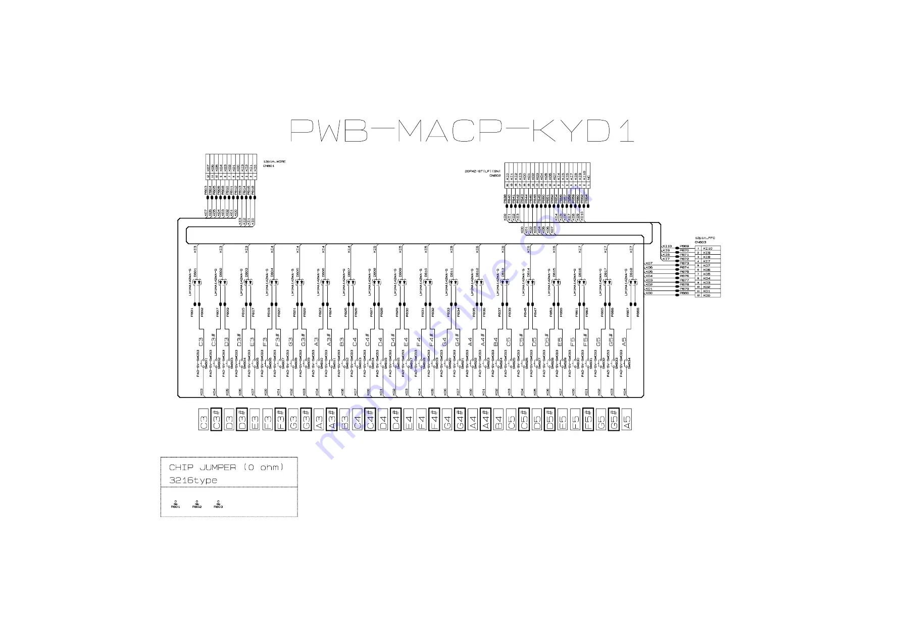
Keyboard PCB MACP-KYD1

(to KYC1/CN601)

(to MDA1/CN2)

(to KYC2/CN602)

Summary of Contents for Privia PX-330BK

Page 1: ...ELECTRONIC KEYBOARD without price PX 330BK PX 330WE AUG 2009 SEP 2011 PX 330BK Ver 5 Sep 2011 INDEX ...

Page 2: ...CONTENTS SPECIFICATIONS 1 BLOCK AND WIRING DIAGRAM 3 PCB LAYOUT 4 CIRCUIT DESCRIPTION 5 PRINTED CIRCUIT BOARDS 7 DISASSEMBLY 13 DIAGNOSTIC PROGRAM 42 EXPLODED VIEW 51 PARTS LIST 53 SCHEMATIC DIAGRAMS 61 ...

Page 3: ...ions Real time recording playback Number of Songs 5 Number of Tracks 17 System Track Tracks 01 through 16 Capacity Approximately 50 000 notes total Up to approximately 10 000 notes per song Punch in recording Pedals Damper Soft Sostenuto switchable Other Functions Transpose 1 octave 12 to 00 to 12 Tuning A4 440 0 Hz 99 cents Octave Shift 2 octaves Temperaments 17 types Stretch Tune Panel Lock MIDI...

Page 4: ... Requirements AC Adaptor AD A12150LW Power Consumption 12 V 18 W Dimensions 132 2 W 28 6 D 13 5 H cm 52 1 16 11 1 4 5 5 16 inch Weight Approximately 11 6 kg 25 6 lbs Based on 1 KB 1024 bytes 1 MB 10242 bytes Specifications and designs are subject to change without notice ...

Page 5: ...DAC IC13 BUTTON CONTROLLER LSI1 LCD LCD CONTROLLER LSI2 HEADPHONE AMPLIFIER IC201 FILTER IC204 FILTER IC205 POWER AMPLIFIER IC202 SDRAM 256 Mbit IC2 SRAM 2 Mbit IC3 VD3 VCP VA3 VD5 VD5 LOUT ROUT VA12 VA5 POWER SUPPLY CIRCUIT Q7 C107 C113 POWER SUPPLY CIRCUIT IC203 Q207 D203 D204 C231 C233 C237 C239 KEY CONTROLLER IC14 MAIN PCB M900 MDA1 SUB PCB M900 PSA1 CONSOLE PCB M901 LCA1 CONSOLE PCB M901 CNA1...

Page 6: ...PCBs M901 LCA1 LCD LCD Controller Button Controller M901 CNA1 Buttons M901 CNA2 Buttons Volume PCB M901 CNA3 Main Volume Jack PCBs M901 JKA1 LINE IN Jacks LINE OUT Jacks M900 HPA1 PHONES Jacks SD Card PCB M810 SDA1 SD Card Slot Keyboard PCBs MACP KYA1 MACP KYC1 Keyboard MACP KYA2 MACP KYC2 MACP KYB1 MACP KYD1 MACP KYB2 MACP KYA1 MACP KYA2 MACP KYB1 MACP KYB2 MACP KYC1 M901 JKA1 M900 PSA1 M900 HPA1...

Page 7: ... A5 A5 B5 C6 SI7 F5 F5 G5 G5 A5 A5 B5 C6 FI8 C6 D6 D6 E6 F6 F6 G6 G6 SI8 C6 D6 D6 E6 F6 F6 G6 G6 FI9 A6 A6 B6 C7 C7 D7 D7 E7 SI9 A6 A6 B6 C7 C7 D7 D7 E7 FI10 F7 F7 G7 G7 A7 A7 B7 C8 SI10 F7 F7 G7 G7 A7 A7 B7 C8 KO0 KO1 KO2 KO3 KO4 KO5 KO6 KO7 KI0 A03 A0 3 B03 C13 C1 3 D13 D1 3 E13 KI1 F13 F1 3 G13 G1 3 A13 A1 3 B13 C23 KI2 C2 3 D23 D2 3 E23 F23 F2 3 G23 G2 3 KI3 A23 A2 3 B23 C33 C3 3 D33 D3 3 E33 ...

Page 8: ...OP PLAY STOP VARIATION FILL IN FF TEMPO DOWN KI1 ACCOMP ON OFF PART NORMAL FILL IN REW TEMPO UP SYNCHRO ENDING PAUSE KI2 RECORDER POPS JAZZ MUSIC PRESET RHYTHM USER SONGS BALLAD PIANO RHYTHMS RHYTHM EDITOR KI3 LATIN WORLD MUSIC PRESET METRONOME USER RHYTHMS RHYTHM EDITOR 2KC0 2KC1 2KC2 2KC3 2KC4 2KI4 GRAND PIANO MODERN ORGAN ELEC PIANO BASS GUITAR STORE USB DEVICE MODE 2KI5 STRINGS SYNTH PAD GRAND...

Page 9: ... 7 PRINTED CIRCUIT BOARDS Main PCB M900 MDA1 Sub PCB M900 PSA1 Console PCB M901 LCA1 ...

Page 10: ... 8 Console PCB M901 CNA1 Console PCB M901 CNA2 Console PCB M901 CNA3 ...

Page 11: ... 9 Jack PCB M900 HPA1 SD Card PCB M810 SDA1 Jack PCB M901 JKA1 Keyboard PCB MACP KYA1 ...

Page 12: ... 10 Keyboard PCB MACP KYA2 Keyboard PCB MACP KYB1 ...

Page 13: ... 11 Keyboard PCB MACP KYB2 Keyboard PCB MACP KYC1 ...

Page 14: ... 12 Keyboard PCB MACP KYC2 Keyboard PCB MACP KYD1 ...

Page 15: ...nel 1 Undo 16 screws and remove eight L COVERs on the bottom surface of the main unit 2 You will see a screw inside when you remove an L COVER Undo and remove the screw through each opening eight screws in total NOTE Do not drop the screws inside the main unit NOTE Do not touch the hammer with the screwdriver while loosening the screws L COVER ...

Page 16: ... screws on the left side case 6 Remove the left side case NOTE The power switch the M900 HPA1 PCB and the pitch bend are assembled to the left side case Do not pull the left side case forcibly 7 Undo and remove two screws from each side case S CASE IL and S CASE IR Left side case Pitch bend M900 HPA1 PCB Power switch Right side case ...

Page 17: ... 15 8 Remove the main panel ...

Page 18: ...may have to remove cable ties or clips If you remove cable ties or clips be sure to tie cables back to the original conditions when reassembling Where to tie bundle cables Power switch M900 HPA1 Left speaker Left tweeter Right speaker Right tweeter ...

Page 19: ...or connected to the lower case 4 Remove the tape fixing the pedal connector cable in place 5 Undo the screw below the USB jack on the back of the main unit 6 Undo five screws and then remove the main PCB M900 MDA1 Tape FFC Keyboard Connector Pitch bend Connector M900 PSA1 Connector M901 LCA1 Connector M810 SDA1 Pedal connector ...

Page 20: ... below for its position Caution when replacing with a new part To attach sponge to the cable to the M901 JKA1 PCB refer to the illustration below for its position 10 5 mm 10 5 mm Removing the jack PCB M901 JKA1 1 Disconnect the M901 JKA1 PCB from the M900 PSA1 PCB by disengaging the connector between them 2 Undo two screws and then remove the M901 JKA1 PCB ...

Page 21: ...ews next to the MIDI jack on the back of the main unit 2 Remove the jack bracket Jack bracket 3 Remove six connectors Connector Right speaker Connector Left speaker Connector Left Tweeter Connector Power switch Connector Right Tweeter Connector M900 HPA1 ...

Page 22: ...NA3 PCB 5 Undo six screws and then remove the M900 PSA1 PCB FFC M900 PSA1 M901 CNA3 PCB M900 PSA1 PCB 10 5 mm Caution when replacing with a new part To attach sponge to the cable to the M900 PSA1 PCB refer to the illustration below for its position ...

Page 23: ...B 2 Undo 12 screws on the M901 CNA2 PCB 3 Undo four screws on the M901 LCA1 PCB NOTE The spacer may come loose in this step Be sure to place the spacer back in place when reassembling 4 Remove the M901 CNA1 PCB M901 CNA2 PCB and M901 LCA1 PCB Spacer M901 CNA1 PCB M901 LCA1 PCB M901 CNA2 PCB ...

Page 24: ... LCA1 PCB and remove the M901 CNA1 PCB and the M901 CNA2 PCB Removing the buttons Once the M901 CNA1 and the M901 CNA2 PCBs are removed you may disassemble the buttons the LED cover the LED spacer and the nonwoven band FFC M901 CNA1 FFC M901 CNA2 ...

Page 25: ...b on the front of the main panel Removing the SD card PCB M810 SDA1 1 Undo four screws and then remove the M810 SDA1 NOTE When reassembling be sure to run the FFC through the ferrite core 2 Undo three screws and then remove the M901 CNA3 PCB Ferrite core Volume knob ...

Page 26: ... the left side case and disengage the jack PCB M900 HPA1 and the power switch Power switch M900 HPA1 PCB Caution when replacing with a new part To attach sponge to the cables to the M900 HPA1 PCB and the power switch refer to the illustration below for its position 50 mm 100 10 mm ...

Page 27: ...d cable NOTE When reassembling be sure to wrap the ferrite core around the pitch bend cable 2 Undo two screws and then remove the pitch bend Ferrite core Caution when replacing with a new part To attach sponge to the cable to the pitch bend refer to the illustration below for its position 0 10 mm 0 10 mm 25 10 mm ...

Page 28: ...crews and then remove the tweeter 2 Similarly remove the other tweeter Caution when replacing with a new part To attach sponge to the cable to the tweeter refer to the illustration below for its position LEFT RIGHT 20 5 mm 20 5 mm 20 5 mm ...

Page 29: ...speaker cover 3 Undo four screws and then remove the speaker 4 Similarly remove the other speaker Caution when replacing with a new part To attach sponge to the cable to the speaker refer to the illustration below for its position Hooks Speaker cover LEFT RIGHT 60 10 mm 50 10 mm ...

Page 30: ...hree screws from either side case S CASE IL and S CASE IR and then remove both side cases 2 Undo 26 screws on the bottom of the main unit 3 Place the main unit with the keys facing up 4 Undo three screws and then remove the KY ASSY KY ASSY ...

Page 31: ...ing black keys Tool The tool used in the photos in this section was converted from a gardening ID tag The size and shape of an ID tag accord to the dimensions below Note on shaping an ID tag The thickness of the tool must be within 1 2 1 3 mm If the tool is too thin removing keys become difficult If the tool is too thick it may damage the rib of the chassis Tool dimensions Width 15 20 mm R 2 75 mm...

Page 32: ...he two tools between the rib of the chassis and a key 2 When the tools are inserted to a certain depth the key begins to be lifted and can then be removed Cross section image Tools Chassis Tool Key Rib of the chassis ...

Page 33: ... the foot of each key C SA E G D B F A B C D E F G A C E G B D F A B C D E F G A C E G B D F A B C D E F G A C E G B D F A B SC Install a black key before installing the white keys on either of its sides Follow the same procedures below to install a black or white key 1 Assemble a key to a hammer 2 Press the protrusion of the chassis firmly into the keyhole 3 Press the key to see if it moves prope...

Page 34: ...n PX 330WE since the beginning of mass production Old hammer New hammer Removing the hammers 1 Place the chassis upside down so that the hammers are visible 2 Press the chassis with the tip of tweezers 3 While catching a hammer with tweezers set the tweezers against the resin part of the chassis 4 Using the chassis tweezer contact as a fulcrum point press down against the resin part in the directi...

Page 35: ...f Hammer W for a white key B for a black key Hammer Code The hammers for white keys are coded W1 W2 W3 and W4 The hammers for black keys are coded B1 B2 B3 and W4 Location to install the hammer A hammer must be installed at the correct location according to its type The combination of hammers and keys are shown below W1 13 keys Hammers for white keys Hammers for black keys B1 9 keys B2 9 keys B3 9...

Page 36: ...te keys 1 Use the tweezers to set a hammer at its correct location 2 Press the chassis with the tip of tweezers 3 Using the chassis tweezers contact as a fulcrum point press down the metal part of the hammer in the direction of the red arrow in the illustration below and then install the hammer NOTE When installing do not damage the felt Be careful not to damage the felt Press down against the met...

Page 37: ...KYC2 KYD1 1 Remove eight rubber keys NOTE One rubber key is shorter than the others 2 Remove the nonwoven tape 3 Remove 23 screws Rubber keys Short rubber key Rubber keys Short rubber key Nonwoven tape MACP KYC1 PCB MACP KYD1 PCB MACP KYC2 PCB ...

Page 38: ... FFC connected on the back of the MACP KYD1 PCB Unlock the connector to remove the FFC and then disengage the MACP KYC1 PCB the KYC2 PCB and the MACP KYD1 PCB FFC MACP KYC1 PCB MACP KYD1 PCB MACP KYD1 PCB MACP KYC2 PCB ...

Page 39: ...ort rubber key at the correct location Lightly insert the tip of a rubber key into the PCB first and then press it in using the end of a paper clip Do not press the rubber key forcefully to avoid damaging the rubber key 3 Secure the MACP KYC1 PCB the KYC2 PCB and the MACP KYD1 PCB with 23 screws Press the PCBs lightly in the direction of the red arrow in the illustration below while tightening a s...

Page 40: ...d the MACP KYB1 2 Remove 26 screws 3 Unlock the connector and disengage the FFC connected to the MACP KYB1 PCB NOTE When removing the FFC be careful not to pull it too much in the direction of the red arrow in the illustration or the PLATE on the back may come loose FFC Nonwoven tape MACP KYA1 PCB MACP KYA2 PCB MACP KYB1 PCB MACP KYB2 PCB MACP KYB1 PCB FFC ...

Page 41: ... keys Short rubber key Before change After change PLATE Before change If the PLATE comes off The PLATE is a transparent plastic plate If the plate comes off put it on the place where the FFC is and insert its end into place where the blue line is shown in the image NOTE The design of the PLATE was modified after the mass production The new types of plates are installed in PX 330WE since the beginn...

Page 42: ...ction of the red arrow in the illustration or the PLATE on the back may come loose MACP KYB1 PCB FFC If the PLATE comes off The PLATE is a transparent plastic plate If the plate comes off put it on the place where the FFC is and insert its end into place where the blue line is shown in the image NOTE The design of the PLATE was modified after the mass production The new types of plates are install...

Page 43: ...Bs the contact with the rubber keys may come out of alignment Align them against the red dotted line in the illustration below lift the PCB once in the direction of the red arrow and then place them again 5 Secure the MACP KYA1 KYA2 PCBs and the MACP KYB1 KYB2 PCBs with 26 screws Press the PCBs lightly in the direction of the red arrow in the illustration below while tightening a screw ...

Page 44: ... sold separately 3 Main volume MAX 4 Have a PC and a USB cable ready They will be used in the USB check Operating System Windows XP SP2 or later 1 Windows Vista 2 Windows 7 3 Mac OS X 10 3 9 10 4 11 or later 10 5 6 or later 10 6 6 or later 1 Windows XP Home Edition Windows XP Professional 32 bit 2 Windows Vista 32 bit 3 Windows 7 32 bit 64 bit How to start the diagnostic program 1 Hold down the FU...

Page 45: ... program RAM check 1 Press the MODERN button to perform the RAM check The confirmation chord C6 sounds and OK appears on the LCD ROM check and Flash Memory check Check SUM test Read Write test 1 Press the CLASSIC button to perform the ROM check The confirmation chord C6 sounds and OK appears on the LCD 2 Press the STORE button to perform the Flash Memory check Check SUM test The check will be comp...

Page 46: ...Left Right ACCOMP 2 Press the STORE button Check that the following LEDs are lit RECORDER RHYTHM USER SONGS POPS JAZZ LATIN WORLD BALLAD PIANO RHYTHMS USER RHYTHMS 3 Press the STORE button Check that the following LEDs are lit MODERN CLASSIC ELEC PIANO VIBES CLAVI ORGAN STRINGS SYNTH PAD BASS GUITAR VARIOUS GM TONES ROM VERSION IROM 01 00 FLSH 01 00 SUBC 01 00 TestMode MX901 LED CHECK LEFT BLOCK T...

Page 47: ...eck that the following LEDs are lit REPEAT PAUSE PLAY STOP Right ACCOMP RECORDER RHYTHM POPS JAZZ TONE FUNCTION REVERB CHORUS SPLIT MODERN LCD check 1 Press the ORGAN button to perform the LCD check Check that all dots are lit 2 Press the STORE button Check that all dots are turned off TestMode MX901 LED CHECK RIGHT BLOCK TestMode MX901 LED CHECK SPEC MAX ...

Page 48: ...illustration below If the button function is OK The confirmation chord C6 sounds and the button number will be displayed If a button function is not operating properly or a button is pressed in a wrong order An error tone F2 sounds and the button number will be displayed 01 02 03 04 05 06 07 08 12 13 14 15 09 10 11 16 24 25 26 27 28 29 30 31 32 17 18 19 20 21 22 23 3 Press the STORE button the las...

Page 49: ...l to the original position The message shown in the right appears Key check Check all white and black keys 1 Press the REPEAT button to select the Key check 2 Confirm that a test tone approx 500 Hz sounds from the left speaker while a key is pressed half way 3 Confirm that a test tone approx 500 Hz sounds from the left speaker and a high pitched test tone approx 2 kHz sounds from the right speaker...

Page 50: ...nfirmation chord C4 sounds Pedal Check for SP 32 1 Press the SOFT pedal The confirmation chord E4 sounds 2 Press the SOSTENUTO pedal The confirmation chord G4 sounds 3 Press the DAMPER pedal ON HALF The confirmation chord C4 sounds 4 Press the DAMPER pedal firmly ON FULL The confirmation chord C4 sounds Sf00 St00 Dp00 BenderOK Note00 Vel00 Sf7F St00 Dp00 BenderOK Note00 Vel00 Sf00 St00 Dp7F Bender...

Page 51: ...and the message shown in the right appears 3 Disconnect the MIDI cable USB check 1 Connect PX 330 to the computer with a USB cable 2 Press the BALLAD PIANO RHYTHM button to perform the USB check The confirmation chord C6 sounds and the message shown in the right appears 3 Disconnect the USB cable SD Card check 1 Insert an SD card into the SD card slot 2 Press the USER RHYTHMS button to perform the...

Page 52: ...ION REVERB CARD INTERNAL MODERN CLASSIC ELEC PIANO STRINGS SYNTH PAD BASS GUITAR VARIOUS GM TONES 2 Release the NO YES and STORE buttons All the LEDs turn off except TONE and REVERB LEDs 3 Press the REVERB button The REVERB and STRINGS SYNTH PAD LEDs are lit 4 Press the STRINGS SYNTH PAD button The REVERB and BASS GUITAR LEDs are lit 5 Press the BASS GUITAR button The REVERB and VARIOUS GM TONES L...

Page 53: ...TTON LEDs 33 19 20 21 19 20 21 18 22 27 29 32 28 23 24 36 12 11 1 2 39 15 4 7 41 44 46 47 48 49 44 51 42 41 40 42 44 45 41 43 49 44 46 50 6 5 3 15 14 14 10 9 8 6 13 18 17 38 37 34 22 26 39 25 27 31 26 30 32 16 35 1 35 2 35 3 35 2 ...

Page 54: ...2 70 65 68 66 69 63 56 56 63 85 85 67 72 76 73 77 78 80 83 82 81 84 62 64 63 64 56 57 59 53 55 61 58 54 60 83 82 81 84 103 85 93 90 87 101 104 100 102 102 86 94 95 91 92 97 97 98 97 100 101 90 89 88 100 99 96 103 71 75 74 79 79 ...

Page 55: ...spare parts department if you need these parts for refurbish 1 Prices and specifications are subject to change without prior notice 2 As for spare parts order and supply refer to the GUIDEBOOK for Spare parts Supply published separately 3 The numbers in item column correspond to the same numbers in drawing PARTS LIST PX 330BK PX 330WE ...

Page 56: ... 1 1 1 1 C IC2 10333111 MEMORY MD56V82160 6TAZ03B 1 1 1 1 1 1 1 1 C D31 10276977 DIODE L1SS400T1G 1 1 1 1 1 1 1 1 X L39 10193074 COIL DLW21HN181SQ2L 1 1 1 1 1 1 1 1 X Q8 Q9 69409403 TRANSISTOR 2SA1576AT106R 2 2 2 2 2 2 2 2 X Q7 22592764 TRANSISTOR 2SB1188T100Q 1 1 1 1 1 1 1 1 X Q10 69300298 TRANSISTOR 2SC4081T106R 1 1 1 1 1 1 1 1 X X1 X31 10334293 RESONATOR 9C12000163 2 2 2 2 2 2 2 2 X SUB PCB PSA...

Page 57: ... D203 10210387 DIODE RSX101VA 30TR 1 1 1 1 1 1 1 1 X D201 10294394 DIODE SK34A 1 1 1 1 1 1 1 1 X JACK PCB JKA1 N 7 10346443 PCB ASSY JKA1 TK RJM509715 001 1 1 1 1 1 1 1 1 C JKA1 J503 10206815 CONNECTOR JY 6314 01 030 1 1 1 1 1 1 1 1 B LINE OUT L J501 J502 J504 10206816 CONNECTOR JY 6314 01 130 3 3 3 3 3 3 3 3 B LINE IN LINE OUT R L501 L504 10231920 COIL RB53 856397NP 4 4 4 4 4 4 4 4 X CONSOLE PCB ...

Page 58: ...9773 002 1 1 1 1 X N 17 10337025 PANEL RJM509390 001V01 1 1 1 1 X N 17 10404274 PANEL RJM509390 004V01 1 1 1 1 X 18 10341073 COVER ASSY SPEAKER TK RJM509617 001 2 2 2 2 X N 18 10342736 COVER ASSY SPEAKER RJM509617 002V02 2 2 2 2 X 19 10175757 PACKING 10X386 RJM504743 001V01 2 2 2 2 2 2 2 2 X 20 10262597 DOUBLE FACED TAPE 3X50 RJM507716 001V01 2 2 2 2 2 2 2 2 X 21 10145912 FABRIC TAPE 5X16 RJM50370...

Page 59: ...0337055 SPACER LED A RJM509411 001V01 7 7 7 7 7 7 7 7 X N 42 10337056 SPACER LED B RJM509412 001V01 3 3 3 3 3 3 3 3 X N 43 10337057 SPACER LED C RJM509413 001V01 1 1 1 1 1 1 1 1 X N 44 10337051 BUTTON TACT A RJM509408 001V01 4 4 4 4 X N 44 10404273 BUTTON TACT A RJM509408 003V01 4 4 4 4 X N 45 10337029 BUTTON TACT B RJM509396 001V01 1 1 1 1 X N 45 10404268 BUTTON TACT B RJM509396 003V01 1 1 1 1 X ...

Page 60: ... 36 36 36 36 36 36 36 A 66 10135428 WHITE KEY B RJM502794 001V01 1 1 1 1 1 1 1 1 A 67 10135426 WHITE KEY CEGB RJM502862 001V01 7 7 7 7 7 7 7 7 A 68 10135427 WHITE KEY DFA RJM502863 001V01 7 7 7 7 7 7 7 7 A 69 10337004 WHITE KEY SC RJM502796 003V03 1 1 1 1 1 1 1 1 A 70 10337003 WHITE KEY SA RJM502795 003V03 1 1 1 1 1 1 1 1 A 71 10341062 HAMMER ASSY W1 TK RJM509600 001 13 13 13 13 13 13 13 13 C 72 1...

Page 61: ...SS EF EH3P065M900 1 1 1 1 1 1 1 1 X 93 69245260 BUTTON POWER M340318 001 1 1 1 1 1 1 1 1 X Key top 94 10341075 PWB UNIT M900 HPA1 TK RJM509834 001 1 1 1 1 1 1 1 1 C HPA1 J601 J602 10208979 JACK HEADPHONE JY 3567 01 070 2 2 2 2 2 2 2 2 B L601 L602 10231919 COIL RB53 856396NP 2 2 2 2 2 2 2 2 X N 95 10346440 BENDER ASSY TK RJM504468 007 1 1 1 1 1 1 1 1 X 96 10204256 FERRITE CORE TRCN16 13 1 1 1 1 1 1...

Page 62: ... 1 1 1 1 1 A wihtout AC CORD 10361066 AC CORD UC2LT M006A 1 1 1 1 C US type 10361067 AC CORD EC2LT M002A 1 1 1 1 C EU type 10361068 AC CORD KC2LT M002A 1 1 C Korea type 10361069 AC CORD AUC2LT M002A 1 1 C Australia type 10361070 AC CORD BC2LT M002A 1 1 C UK type 10342718 MUSIC STAND RJM508666 001V04 1 1 1 1 C N 10342719 MUSIC STAND RJM508666 002V04 1 1 1 1 C 10371588 DUST COVER RJM506261 001V02 1 ...

Page 63: ... 61 SCHEMATIC DIAGRAMS Main PCB M900 MDA1 1 2 to LCA1 CN3 to PSA1 CN202 USB to SDA1 CN751 PITCH BEND PEDAL Not used ...

Page 64: ... 62 Main PCB M900 MDA1 2 2 to MDA1 CN6 to KYD1 CN802 to KYB1 CN804 Not used ...

Page 65: ... 63 Sub PCB M900 PSA1 1 2 to POWER SWITCH PEDAL MIDI to MDA1 CN3 to CNA3 CN3 to JKA1 CN501 to RIGHT SPEAKER to RIGHT TWEETER to LEFT SPEAKER to LEFT TWEETER to HPA1 CN601 Not used ...

Page 66: ... 64 Sub PCB M900 PSA1 2 2 Not used ...

Page 67: ... 65 Console PCB M901 LCA1 1 2 to MDA1 CN11 to CNA1 CN601 to CNA2 CN602 Not used ...

Page 68: ... 66 Console PCB M901 LCA1 2 2 Not used ...

Page 69: ... 67 Console PCB M901 CNA1 to LCA1 CN2 ...

Page 70: ... 68 to LCA1 CN1 Console PCB M901 CNA2 ...

Page 71: ... 69 Jack PCB M901 CNA3 Jack PCB M901 JKA1 to PSA1 CN201 Not used to PSA1 CN215 Not used Not used ...

Page 72: ... 70 Jack PCB M900 HPA1 SD Card PCB M810 SDA1 to PSA1 CN206 to MDA1 CN7 ...

Page 73: ... 71 Keyboard PCB MACP KYA1 to KYA2 CN602 ...

Page 74: ... 72 Keyboard PCB MACP KYA2 to KYA1 CN601 to KYB1 CN801 ...

Page 75: ... 73 Keyboard PCB MACP KYB1 to KYA2 CN603 to MDA1 CN1 to KYB2 CN803 ...

Page 76: ... 74 Keyboard PCB MACP KYB2 to KYB1 CN802 ...

Page 77: ... 75 Keyboard PCB MACP KYC1 to KYD1 CN801 ...

Page 78: ... 76 Keyboard PCB MACP KYC2 to KYD1 CN803 ...

Page 79: ... 77 Keyboard PCB MACP KYD1 to KYC1 CN601 to MDA1 CN2 to KYC2 CN602 ...

Page 80: ...P50 Correction of the PARTS LIST P56 P57 Ver 2 Nov 2009 Correction of the DISASSEMBLY P33 Ver 3 Jan 2010 Correction of the PARTS LIST P56 Ver 4 Sep 2011 Addition of the new model PX 330WE Correction of the DISASSEMBLY P31 to P34 P39 and P40 Correction of the DIAGNOSTIC PROGRAM P42 and P50 Correction of the EXPLODED VIEW P51 and P52 Correction of the PARTS LIST P53 to P60 Ver 5 Sep 2011 Correction ...
Reviews: