background image

— 122 —

Model

Name

Board No.

Drawing No.

CASIO COMPUTER CO.,LTD.

QT-6060D
 (EX-DP-UNIT-16)

EDP-1

MAIN BOARD (1/2)

RJE50****

Summary of Contents for QT-6000

Page 1: ...SERVICE MANUAL ELECTRONIC CASH REGISTER without price QT 6000 EX 820 AUG 2004 QT 6000 Ver 3 Mar 2010 ...

Page 2: ...ARTS LIST 125 To prevent malfunctions caused by the weak batteries charge the memory protection batteries for over 12 hours before installation or after a long time vacation over 30 days Before installation initialize the terminal and leave it turn on over 12 hours After a long time vacation initialize the terminal and restore the program data if the terminal is in malfunction and leave it turn on...

Page 3: ...BASE TX PCMCIA controller Name R5C485 LQFP144 Operating temperature 0 C 40 C Operating humidity 20 85 Storage temperature 20 C 65 C Storage humidity 10 85 120V 220V 230V 240V Power consumption AC input current at Adaptor In operation 1 1A 1 1A 1 1A 1 1A Display off 0 25A 0 15A 0 14A 0 13A DC input current at QT 6000 In operation 0 9A 0 9A 0 9A 0 9A Display off 0 5A 0 5A 0 5A 0 5A Memory protection...

Page 4: ... colors Touch Panel Name N010 0550 T711 Size 12 1 inch Panel brightness control 1 x VR controller Speaker 0 5 watt x 1 Microphone Mini electret condenser microphone EM100TW ER Power supply External adaptor ADP820AA Cleck key Magnetic ibutton prove 94 J 04 1 4 Devices specifications Card slot cover PC CARD slot CF CARD slot DC IN PC MODEM SCANNER DISPLAY DRW1 DRW2 COM1 COM4 COM2 COM5 COM3 COM6 SPK ...

Page 5: ...options 1 7 Drawer Type Drawer Name Specification USA Other Countries M DL 2785 D 20BC B84M 15 X M DL 2786 D 20BC B84SM 15 X M DL 2920 D 20BC B87M 15 X M DL 2921 D 20BC B87SM 15 X M DL 2425 D 20BC B55SM 15 X M DL 2525 D 20BC B64SM 15 X L DL 3616 D 11BH B65SS 9 X X L DL 3617 D 11BH B65S 9 X DEVICE NAME MAKER MODEL NOTE Slip printer AC adaptor AD31 U or E U 100V E 200V Remote printer EPSON TM T88 ll...

Page 6: ...Lithiumbatteri Eksplosionsfare ved fejlagtig hándtering Udskiftning má kun ske med batteri af samme fabrikat og type Levér det brugte batteri tilbage til leverandØren 1 8 Duration of Life Panel of TFT LCD 50 000 hours Back Light of TFT LCD 43 000 hours Touch Panel number of touch times 10 million times LCD of customer display option 20 000 hours Back light of customer display option 20 000 hours H...

Page 7: ...pyright C 2004 CASIO COMPUTER CO LTD C All rights reserved ROM VER xxxxxx xxxx 7 8 9 CREATE xxxx xx xx xx xx QT 6000 Version x xx 4 5 6 APL VER xxxxxx xxxx 1 2 3 0 OK 6 After releasing the key enter 20000 U S 10000 other area English 40000 other area German 50000 other area French 60000 other area Spanish and press the OK key ID IP ADDRESS Terminal ID ENTER ID DHCP USE OK Terminal ID 1 32 If you d...

Page 8: ...gram data from other teminal INIT 10 10 01 12 34 000001 AUTO PGM 1 No Restore Receive 2 PGM Restore CF Card 3 PGM Receive Inline All Data including totalizer All PGM program only Select the machine to send the data INIT 10 10 01 12 34 000001 Receive Data All PGM PGM Receive from MC 05 OK YES Restore from CF card Insert the CF card into the slot and select the appropriate file and press the YES key...

Page 9: ... xx xx xx xx QT 6000 Version x xx APL VER xxxxxx xxxx OK 7 Select 1 Flag Clear and press YES key to flag clear or select 2 Init2 and press YES key and enter 8888888888 and YES key to Init 2 2 2 SYSTEM INITIALIZATION In this chapter shows how to install QT 6000 systems and peripherals 2 2 1 How to load IPL Initial Program Loading Normally IPL is not necessary since the terminal has efficient progra...

Page 10: ...4 If you choose COM port or IN LINE port select baud rate of the IPL source device and press the YES key 5 Press the YES key to proceed in case of downloading via inline automatic ID definition is made by this timing So press the YES key terminal by terminal 6 After finishing IPL machine initialization is necessary 1 Turn on this terminal with pressing the initialze switch and release 2 Enter 4444...

Page 11: ...the main unit and the stand 2 Remove one screw and the cover 3 Remove two screws and the cover 4 Remove ten screws 5 Remove one screw and the lid of the software key 6 Remove the wiring for the DRAWER a cable and an earth Screws Screw 10 ...

Page 12: ...emove the REAR CASE Be careful with the REAR CASE when removing it since there is a wiring which connects to the speaker 10 Remove the connector for the speaker 11 Remove four screws and the iron plate 12 Remove three screws 13 Remove four connectors one FPC and the IO unit FPC Connectors Screw 4 Screw 3 CARD SLOT COVER Screws ...

Page 13: ...he connector for the battery and the battery 15 Remove four connectors 15 Remove twelve screws and the metal bracket Connectors 4 FPC 16 Remove three connectors and one FPC Screw 3 Screw 3 Screw 3 Screw 3 Connectors 3 ...

Page 14: ...then remove the main PCB FPC Connectors boss Screw 6 18 Remove 14 screws and then the LCD unit 19 Remove two screws one connector and the inverter PCB 20 Remove four screws and the LCD Screw 14 Screw 2 Connectors Screw 4 The touch panel is fixed by double sided tape ...

Page 15: ...move four screws 2 Release the connector and remove the IO PCB 3 Remove four screws and separate the unit as shown below Screw 4 Connector Screw 4 4 Remove the cap 5 Remove four screws under both packing Screw 2 Screw 2 ...

Page 16: ... 14 6 Release the hook and remove the REAR CASE 7 Remove five screws connector and the HINGE 8 Remove seven screws and separate the LCD Unit Screw 5 Screw 7 ...

Page 17: ...ws 2 Connect the connector and fix the inverter PCB with two screws Screw 2 3 Fix the LCD UNIT to the FRONT CASE with 14 screws Fix the screws from above the earth plate Bind the wirings for the inverter 4 Fix the main PCB with six screws and three bosses FPC Connector Boss 3 Screw 6 ...

Page 18: ...6 5 Connect one PFC and three connector 6 Fix the iron plate with twelve screws Terminal side 7 Connect four connectors Screw 3 Screw 3 Screw 3 Screw 3 15 Remove four connectors Connectors 4 Connectors 3 ...

Page 19: ...t the connector for the battery and assemble the battery 9 Assemble the IO Unit and fix it with three screws Connect four connectors and one FPC FPC Screw 3 10 Fix the iron plate with four screws Screw 4 Connectors ...

Page 20: ...k the REAR CASE and fix it with ten screws 12 Fix the PC CARD and the CF CARD COVER Fix the backup battery cover with one screw Connect the DRAWER wiring a cable and an earth 13 Fix the case with two screws Screw 10 14 Fix the IP PORT COVER and the stand CARD SLOT COVER Screws ...

Page 21: ...seven screws 2 Connect the connector and fix the HINGE with five screws Screw 7 Screw 5 3 After fixing the packing to the REAR CASE assemble the REAR CASE and the FRONT CASE Hooks 4 Remove the LCD unit with four screws Position under both packing Screw 2 Screw 2 ...

Page 22: ...x the cap to the stand Be careful with the direction of the cap The height of the screw hole on the front side should be lower Screw 4 7 Let the connector through the cap and fix the LCD unit with four screws 8 Connect the connector and fix the IO Unit with four screws Screw 4 Connector ...

Page 23: ...hen the metal bracket Type A Type B 3 Connect the cable to EX DP UNIT 16 4 Fix the metal bracket for type A with screws Metal bracket for type B Metal bracket for type A 5 OPTION INSTALLATION 5 1 Installing the display set for customer EX DP UNIT 16 There are two types for the display set for customer EX DP UNIT 16 ...

Page 24: ...xed Align the metal bracket in the center of the main unit and fix it where it is 1 0cm from the edge 5 Fix EX DP UNIT 16 to the main unit with four screws 6 Connect the cable to the main unit COM3 7 Fix the metal bracket which was removed in the above step 2 4 Fix the main unit to the metal bracket for type B 5 Connect the cable to the main unit COM3 6 Fix the metal bracket which was removed in t...

Page 25: ...e fixed in STD POLE This separates DP STAND ASSY 3 Remove four tapping screws to remove the chas sis from the STAND ASSY 4 Fix STD POLE and ROTARY SHAFT to DP ASSY with four pan head screws 5 Fix the part arranged by dealers It is possible to attach the long pole in QT 6060D Please arrange the following parts at your side when you need them Reference Drawing ...

Page 26: ...ble the lead wire earth into the connector 5 Wind the lead wire around the core twice and then connect the core to the connector of the main unit 5 2 To install the I Button 1 Remove the REAR COVER for QT 6000 No 1 to No 10 in the disassembly procedure 2 Remove one screw and then the I Button cover ...

Page 27: ...he main unit 3 Insert the MCR into the special metal bracket NOTE Be careful not to damage the FPC 4 Connect the connector and fix the metal bracket with two screws NOTE The lead wires should be stored neatly in a line FPC 6 Store the core in the main unit and then fix it with fabric tape 5 3 To install the MCR ...

Page 28: ...e holes on the drawer 6 Connect the connector to QT 6000 NOTE Arrange the cables so that they do not tangle with each other Card slot cover PC CARD slot CF CARD slot DC IN PC MODEM SCANNER DISPLAY DRW1 DRW2 COM1 COM4 COM2 COM5 COM3 COM6 SPK MIC LAN1 VOL COM1 COM4 COM2 COM5 COM3 COM6 From the AC adaptor Inline 10 100Base T Drawer 2 Drawer 1 Ext microphone Ext speaker 5 Fix the metal bracket to QT 6...

Page 29: ... cluster Maximum cable length between terminal and terminal via hubs is 300m CAT5 cable specifications CAT5 UTP Cable Straight 0 5mm x 4P Not shielded wire Twist pair cable Configuration with Hub 10BASE T 100BASE TX 6 2 Wireless LAN There is a PC CARD SLOT in QT 6000 and a wireless LAN CARD can be installed to the PC CARD SLOT The specifications are as shown below figure The maximum communication ...

Page 30: ... Maximum 3 remote printers in the 1 terminal system 6 remote printers 2 terminal system 8 re mote printers in the 3 32 ter minal can be defined 2 PC Cable wiring PC on line Maximum 32 terminals 2 PC Cable wiring Pin No Signal name 3 SD TXD 2 RD RXD 7 RS RTS 8 CS CTS 1 CD DCD 4 ER DTR 6 DR DSR 9 CI RI 5 GND QT 6000 Com1 MODEM DSUB25 Pin No Signal name 2 SD 3 RD 4 RS 5 CS 8 CD 20 ER 6 DR 22 CI 7 GND...

Page 31: ...MOTE DISP to COM3 When desiring to conduct a test for an unlimited number of times enter a value other than 0 in accordance with the explanation for each test Tests are performed for an unlimited number of times when a value of 1 through 9 is entered for the commend used to specify the number of times testing is performed in the operating procedure on each page However this function allows a test ...

Page 32: ...rawer Open close status MAC address MAC address CF Insertion status DISP ON OFF switch Switch status Wireless LAN card Insertion status TEMP Power supply A D conversion value Display only updated when DISP ON OFF switch is ON DALLAS DRW1 CLOSE MAC ADRS XX XX XX XX XX XX RF INSERT CF INSERT DISP ON OFF ON TEMP 20 Diag Ver XXXXXX XXXX DRW2 CLOSE 0000 1234 Status information is displayed continuously...

Page 33: ... test pn313 36 11 LCD test n021 37 12 LCD calibration test 221 38 13 Back light OFF test 121 38 14 Remote Cust DISP test bn023 39 15 External printer print test x1x2x3n03d 40 16 RS232C PORT test xn04d 41 17 RS232C PORT batch test 40 42 18 Ethernet test m0a51 43 19 MAC Address SET x0951 44 20 Wireless LAN test m0a52 45 21 Time setting x1x2x3x4x5x60a70 46 22 Time display 70 46 23 Drawer open test xn...

Page 34: ...printed BATC H 2 RAM WR OK FLASH CHK SUM OK DATE 01 12 31 TIME 23 59 30 Please Hit Key OK 1 NG 9 DRW ALL OK END 2 Print When normally printed 2 Batch test 2 Function LCD display test and backlight test are performed continuously Operation Refer to the page for the details of the following tests Operation 3 ST The following tests are performed automatically 1 LCD test Enters the wait mode for the i...

Page 35: ...nts the address of the error in case the test ended with an error RAM n011 RAM WR NG END n011 4 RAM READ ONLY test Function READ ONLY test for RAM is performed Note that WRITE test n011 must be performed right before this test Operation Operation n 1 1 1 ST n 0 1 One time check can be omitted not 0 Continuous check To stop the test press ESC key LCD RAM n111 RAM RD OK END n111 RAM n111 RAM RD OK E...

Page 36: ... deleting the memory by CLEAR WRITE READ test is performed Note since this test cannot backup the program you need to perform IPL again after the test When the memory in the FLASH memory is cleared by the CLEAR test the program is cleared also Operation Operation n 6 1 2 ST n 0 1 One time check can be omitted not 0 Continuous check To stop the test press ESC key LCD NG and the address are displaye...

Page 37: ...F WR OK END pn013 CF pn013 CF WR OK END pn013 NG and the address are printed if WRITE cannot be done normally 8 CF CARD READ ONLY test Function This test will check the read only test for CF CARD Perform the CF CARD write test before start of this test Note that this test does not ensure the data inside the CF CARD as well as its performance Operation Operation p n 1 1 3 ST p designates PCMCIA SLO...

Page 38: ...OK END pn213 CF CARD pn213 CF CLR OK END pn213 PRINT 10 CF CARD CLEAR WRITE READ test Function The CLEAR WRITE READ test for CF CARD is performed After deleting the memory by CLEAR WRITE READ test connection test is performed Note that this test does not ensure the data inside the CF CARD as well as its performance Operation Operation p n 3 1 3 ST p designates PCMCIA SLOT 0 CF 1 PCMCIA n 0 One tim...

Page 39: ...o stop the test press ESC key LCD Green Blue Reverse check Red White Black Touch any place in the panel Touch any place in the panel Touch any place in the panel Touch any place in the panel Touch any place in the panel Touch any place in the panel Check black and white Shows the following colors and patterns in the display in the order of black white red green blue check and reverse check Returns...

Page 40: ...de even when the product is in the market Make sure to backup the register data when necessary Operation A cross appears at the following four coordinates in the panel one by one When a cross at a certain coordinate is touched the next coordinate will show another cross there X Y 100 100 100 500 700 100 700 500 Operation 2 2 1 ST LCD TOUCH START 221 X1 Y1 XXX XXX X2 Y2 XXX XXX X3 Y3 XXX XXX X4 Y4 ...

Page 41: ...ng one time check OK 1 NG 9 Operation b n 0 2 3 ST b Baud rate selection 0 19 2 Kbps 1 9600 bps n 0 One time check can be omitted not 0 Continuous check To stop the test press ESC key When performing continuous check the same test character data is sent at a certain interval When the test is ended manually upon the input of ESC key the display is cleared and the backlight turns off In case of one ...

Page 42: ...ntinuous check To stop the test press ESC key d Printer type selection 1 RJ 2 SLIP Note that some printers cannot use certain baud rates Refer to the list below When changing the baud rate make sure to change the setting for the printer also A pattern B pattern 19 2 Kbps 9600 bps 4800 bps SLIP PRINTER SP1300 Ο Ο RJ PRINTER UP250 350 360 Ο Ο Ο BBBBBBBBBBBBBBBBBBBBB 8 888 88 BBBBBBBBBBBBBBBBBBBBBBBB...

Page 43: ...rate selection 0 2400 bps 1 4800 bps 2 9600 bps 3 19 2 kbps 7 115 kbps COM 1 only n 0 One time check can be omitted not 0 Continuous check To stop the test press ESC key d Port selection 1 COM1 2 COM2 3 COM3 4 COM4 5 COM5 6 COM6 LCD COM 41 RTS1 1 CTS1 1 OK DTR1 1 DSR1 1 OK DTR1 1 CD1 1 OK DTR1 1 CI1 1 OK RTS1 0 CTS1 0 OK DTR1 0 DSR1 0 OK DTR1 0 CD1 0 OK DTR1 0 CI1 0 OK TxD RxD OK END 41 Displays o...

Page 44: ...e time LCD COM BATCH 40 RTS1 1 CTS1 1 OK DTR1 1 DSR1 1 OK DTR1 1 CD1 1 OK DTR1 1 CI1 1 OK RTS1 0 CTS1 0 OK DTR1 0 DSR1 0 OK DTR1 0 CD1 0 OK DTR1 0 CI1 0 OK TxD RxD OK RTS2 1 CTS2 1 OK DTR2 1 DSR2 1 OK DTR2 0 CD2 0 OK DTR2 0 CI2 0 OK TxD RxD OK END 40 COM 1 test result COM 2 test result T x D R x D CTS RT S DTR DSR C D C I T x D R x D CTS RT S DTR DSR COM1 COM2앑COM6 output 1 0 from the output termi...

Page 45: ...e repeats hereinafter Operation Once an ID is set make sure to perform the test using this ID When changing the ID turn the power on again m 0 a 5 1 ST m Own ID as for the designated ID refer to About ID a 1 TCP send mode 2 TCP receive mode 3 UDP send mode 4 UDP receive mode Continue the test unless an error occurs End the test manually by pressing ESC end the send ECR first About ID ID is effecti...

Page 46: ...ration for 48 bits 6 times inputs a 48 bit address and the sixth input of ST writes the address The address inputted in the number display position in 8 bit is then displayed in hexadecimal The inputted address is cleared by the input of CLEAR The test ends without writing an address by the input of ESC when writing MAC address FF8048FF9800 After entering the manual writing mode the above address ...

Page 47: ...ecks only the received data The send ECR a 3 waits for one second and starts sending data again the same repeats hereinafter Operation Once an ID is set make sure to perform the test using this ID When changing the ID turn the power on again m 0 a 5 2 ST m Own ID as for the designated ID refer to About ID a 1 TCP send mode 2 TCP receive mode 3 UDP send mode 4 UDP receive mode Continue the test unl...

Page 48: ...YYMMDD0170 PRINT 23 Drawer open test Function This test will check the drawer open function The test ends by the judgment of the operator either by OK or NG only when the one time check is selected Operation Operation x n 0 9 1 ST x 0 All drawers open can be omitted 1 Drawer 1 open 2 Drawer 2 open n 0 One time check can be omitted not 0 Continuous check To stop the test press ESC key When the cont...

Page 49: ...ND n092 25 OBR test Function This is a scanner test The test enters the wait mode for the scanner input and waits only for scanner The test determines the result between OK and NG by comparing the fixed data and the read data Make sure to connect OBR HHS 15 to COM 2 The fixed barcode is as follows Operation Operation 9 5 ST To stop the test press ESC key LCD PRINT OBR 95 OBR OK OBR ERR xxxxxxxxxxx...

Page 50: ...y to end the test manually LCD MCR1 indicates track 1 while MCR2 indicates track 2 in the display Normally ended both track 1 and 2 MCR 96 MCR1 OK MCR2 OK END 96 MCR2 ERR MCR1 ERR MCR 96 MCR1 OK MCR2 OK END 96 OK when the read data is correct Error example The display shows error when the track 1 has an error The read data is displayed The track 1 ended normally Only the track 2 has an error Only ...

Page 51: ...can be designated in 8 levels 0 to 7 The higher the number is the lower the volume is Note that the number 8 and 9 automatically are changed to 7 x 0 Plays back the sound which was recorded by the command 98 1 to 9 Plays back the specific sound n 0 One time check not 0 Continuous loop Press ESC key to end the test manually In case of one time check only OK and NG keys below can be used OK key numb...

Page 52: ...conds followed by the playback of the recorded data at the maximum volume Operation Operation 9 8 ST Press OK or NG key to end the test OK 1 NG 9 LCD 29 Charging test Function This test will turn off the charging function Operation Operation 9 9 ST LCD CAHRGE OFF 99 END 99 CAHRGE OFF 99 END 99 MIKE 98 MIKE OK END 98 MIKE 98 MIKE OK END 98 Print Print ...

Page 53: ...CARDBUS card I F COM1 DSUB9pin Battery main pcb 5V Supply COM2 SIGNAL ONLY Disp On Off SDRAM E820 1 MCR I O ctrl G A Sound BGA256pin BGA90pin EtherNet MODEM or PC COM4 6 DSUB9pin x3 SPEAKER Out MIC in Green DL POWER CORD DSUB9pin DSUB9pin AC adaptor unit type LPS Casio Drawer2 HUB SPEAKER OU SIGNAL ONLY CAT 5 UTP cable DL FPC harness FFC Optional Printer etc MIC in POWER SUPPLY UNIT Power Status C...

Page 54: ...inch TOUCH PANEL DALLAS KEY DISPLAY ON OFF SW DRAWER PORT X 2 SOFT WARE KEY LCDC IC IC45 SERIAL I F 3 3V 5V PCMCIA IC IC36 PCI CARD CPU SH 4 SH 7751R 240MHz IC26 I O CONTROLLER 78K4 12 5MHz IC44 PC CARD SLOT CARD BUS IEEE802 11b IEEE802 11g BUFFER IC4 5 6 7 RS232C 1 COM1 CF CARD SLOT Ethernet IC IC28 EEP ROM IC35 LAN PORT ADPCM IC IC15 Amplifier IC IC18 MIC Sound Speaker RTC IC19 RS232C 5 COM2앑6 G...

Page 55: ...The reset circuit is as follows 8 4 POWER SUPPLY CIRCUIT 1 VP DC 19V For the drawer circuit VOP DC 5 2V For the COM2 3 power and display ON OFF LED VCC DC 5V For the logic circuit power The power supply circuit is as follows ...

Page 56: ...WER SUPPLY CIRCUIT 2 VBAT DC 3 3V For the battery V1 5 DC 1 5V For the CPU core V1 8 DC 1 8V For the PCMCIA core The power supply circuit is as follows 8 6 DRAWER I F CIRCUIT The drawer open circuit is as follows ...

Page 57: ...3 D22 D21 D20 D19 D18 D17 D16 DQM3 DQM2 A17 A16 A15 A14 A13 A12 1 2 3 4 5 6 7 8 9 10 11 12 13 14 15 16 17 18 19 20 21 22 23 24 25 26 27 28 29 30 31 32 33 34 35 36 37 38 39 40 41 42 43 44 45 46 47 48 49 50 51 52 53 54 55 56 57 58 59 60 61 62 63 64 TMS TCK TDI D0 D1 D2 D3 D4 D5 D6 D7 D8 D9 D10 D11 D12 D13 D14 D15 DQM0 DQM1 RD CKIO Reserved Reserved CKE A0 A1 A2 A3 A4 A5 A6 A7 A8 A9 A10 A11 192 191 1...

Page 58: ...s data Peripheral data bus UBC 32 bit data store 32 bit data load CPU I cache O cache ITLB UTLB Cache and TLB controller FPU BSC Bus state controller CPG Clock pulse generator DMAC Direct memory access controller FPU Floating point unit INTC Interrupt controller ITLB Instruction TLB translation lookaside buffer UTLB Unified TLB translation lookaside buffer RTC Realtime clock SCI Serial communicati...

Page 59: ... Internal VDD 18 VSS Power Internal GND 19 D1 20 D2 21 D3 22 D4 23 D5 I O Data 24 D6 25 D7 26 D8 27 D9 28 D10 29 VDDQ Power IO VDD 30 VSSQ Power IO GND 31 D11 32 D12 33 D13 I O Data 34 D14 35 D15 36 CAS0 DQM0 O D7 D0 select signal 37 CAS1 DQM1 O D15 D8 select signal 38 RD WR O Read write 39 CKIO O Clock output 40 Reserved Do not connect 41 VDDQ Power IO VDD 42 VSSQ Power IO GND 43 Reserved Do not ...

Page 60: ...ignal 75 D16 76 D17 I O Data 77 D18 78 D19 79 VDDQ Power IO VDD 80 VSSQ Power IO GND 81 VDD Power Internal VDD 82 VSS Power Internal GND 83 D20 84 D21 85 D22 86 D23 87 D24 I O Data 88 D25 89 D26 90 D27 91 D28 92 D29 93 VDDQ Power IO VDD 94 VSSQ Power IO GND 95 D30 I O Data 96 D31 97 VDD Power Internal VDD 98 VSS Power Internal GND 99 A18 100 A19 101 A20 O Address 102 A21 103 A22 104 A23 105 VDDQ P...

Page 61: ...nction bus grant 128 SERR I O System error 129 AD31 I O PCI address data port 130 AD30 I O PCI address data port 131 VDDQ Power IO VDD 132 VSSQ Power IO GND 133 AD29 134 AD28 135 AD27 I O PCI address data port 136 AD26 137 AD25 138 AD24 139 C BE3 I O Command byte enable 140 AD23 141 AD22 I O PCI address data port 142 AD21 143 VDDQ Power IO VDD 144 VSSQ Power IO GND 145 VDD Power Internal VDD 146 V...

Page 62: ...O VDD 193 XTAL2 O RTC crystal resonator pin 194 EXTAL2 I RTC crystal resonator pin 195 VDD RTC Power RTC VDD 196 VSS RTC Power RTC GND 197 CA I Hardware standby 198 RESET I Reset 199 TRST I Reset H UDI 200 MRESET I Manual reset 201 NMI I Nonmaskable interrupt 202 BACK BSREQ O Bus acknowledge bus request 203 BREQ BSACK I Bus request bus acknowledge 204 MD6 IOIS16 I Mode IOIS16 PCMCIA 205 RDY I Bus ...

Page 63: ...Data out H UDI 247 VDDQ Power IO VDD 248 VSSQ Power IO GND 249 VDD PLL2 Power PLL2 VDD 250 VSS PLL2 Power PLL2 GND 251 VDD PLL1 Power PLL1 VDD 252 VSS PLL1 Power PLL1 GND 253 VDD CPG Power CPG VDD 254 VSS CPG Power CPG GND 255 XTAL O Crystal resonator 256 EXTAL I External input clock crystal resonator I Input O Output I O Input output Power Power supply Notes 1 Except in hardware standby mode supp...

Page 64: ...A9 P50 A8 P47 AD7 P46 AD6 P45 AD5 P44 AD4 P43 AD3 P42 AD2 P41 AD1 P40 AD0 P87 A7 P86 A6 P85 A5 P84 A4 P83 A3 P95 P94 P93 P92 P91 P90 TEST V PP P37 EXA P36 TI01 P35 TI00 P34 TI2 P33 TI1 P32 TO2 P31 TO1 P30 TO0 P103 TI8 TO8 P102 TI7 TO7 P101 TI6 TO6 P100 TI5 TO5 V DD P67 ASTB P66 WAIT P65 WR P64 RD P63 A19 P11 ANI1 P12 ANI2 P13 ANI3 P14 ANI4 P15 ANI5 P16 ANI6 P17 ANI7 AV SS P130 ANO0 P131 ANO1 AV RE...

Page 65: ...TROL A D CONVERTER AVDD AVSS P03 NMI INTP2 PCL BUZ AVREF0 ANI0 ANI7 D A CONVERTER ANO0 AVSS AVREF1 ANO1 78K IV CPU CORE ROM RAM BAUD RATE GENERATOR RxD1 SI1 TxD1 SO1 ASCK1 SCK1 RxD2 SI2 TxD2 SO2 ASCK2 SCK2 SI0 SO0 SCK0 BUS I F UART IOE1 RD ASTB WR WAIT A0 A7 AD0 AD7 A8 A15 A16 A19 PORT1 P10 P17 PORT0 P00 P06 PORT2 P20 P27 PORT3 P30 P37 PORT4 P40 P47 PORT5 P50 P57 PORT6 P60 P67 PORT7 P70 P72 PORT8 ...

Page 66: ...ANI0 26 P11 ANI1 27 P12 ANI2 28 P13 ANI3 29 P14 ANI4 30 P15 ANI5 31 P16 ANI6 32 P17 ANI7 33 AVSS A D CONVERTER D A CONVERTER GND 34 P130 ANO0 35 P131 ANO1 36 AVREF1 Application of Standard Voltage for D A CONVERTER 37 P70 RxD2 SI2 38 P71 TxD2 SO2 39 P72 ASCK2 SCK2 40 P20 RxD1 SI1 41 P21 TxD1 SO1 42 P22 ASCK1 SCK1 43 P23 PCL 44 P24 BUZ 45 P25 SI0 SDA0 46 P26 SO0 47 P27 SCK0 SCL0 48 P80 A0 49 P81 A1...

Page 67: ... 75 P62 A18 76 P63 A19 77 P64 RD 78 P65 WR 79 P66 WAIT 80 P67 ASTB 81 VDD Power Supply 82 P100 TI5 TO5 83 P101 TI6 TO6 84 P102 TI7 TO7 85 P103 TI8 TO8 86 P30 TO0 87 P31 TO1 88 P32 TO2 89 P33 TI1 90 P34 TI2 91 P35 TI00 92 P36 TI01 93 P37 EXA 94 TEST VPP TEST pin 95 P90 96 P91 97 P92 98 P93 99 P94 100 P95 IO 8 bit input output PORT IO 8 bit input output PORT IO 8 bit input output PORT IO 8 bit input...

Page 68: ...O DATA D3 105 U2_SOUT O TXD3 34 D4 I O DATA D4 106 U3_CTSB I CTS4 35 D5 I O DATA D5 107 U3_DSRB I DSR4 36 VDD VDD VDD 108 VDD VDD VDD 37 GND GND GND 109 GND GND GND 38 GND GND GND 110 GND GND GND 39 D6 I O DATA D6 111 U3_SIN I RXD4 40 D7 I O DATA D7 112 U3_DTRB O DTR4 41 D8 I O VDD 113 U3_RTSB O RTS4 42 TGND GND GND 114 U3_SOUT O TXD4 43 D9 I O VDD 115 U4_CTSB I VDD 44 D10 I O VDD 116 U4_DSRB I VD...

Page 69: ...A1 A11 RAS Top view DQM1 NC NC CAS WE DQM0 VDDQ DQ8 VSS VDD DQ7 VSSQ VSSQ DQ10 DQ9 DQ6 DQ5 VDDQ VSSQ DQ12 DQ14 DQ1 DQ3 VDDQ DQ11 VDDQ VSSQ VDDQ VSSQ DQ4 DQ13 DQ15 VSS VDD DQ0 DQ2 90 ball FBGA Clock Generator Mode Register Command Decoder Control Logic Row Address Buffer Refresh Counter Column Address Buffer Burst Counter Data Control Circuit Latch Circuit Input Output Buffer DQ DQM CLK CKE Address...

Page 70: ...1 A20 OE N C CE VSS DQ15 DQ14 DQ13 DQ12 VSSQ VCCQ DQ11 DQ10 DQ9 DQ8 VCC A19 A18 A17 A16 A15 A14 A13 Marking Side FPT 56P M01 VCC VSS A22 to A0 RESET WE CE OE WP ACC DQ15 to DQ0 DQ15 to DQ0 Bank A address Bank C Address Bank B Address Bank D address State Control Command Register Status RY BY Control Cell Matrix 16 Mbit Bank A X Decoder Y Gating Cell Matrix 16 Mbit Bank D X Decoder Y Gating Cell Ma...

Page 71: ... 7 8 9 10 11 12 13 14 15 16 17 18 19 20 A B C D E F G H J K L M N P R T U V W Y A B C D E F G H J K L M N P R T U V W Y MD12 MD35 MD36 MD37 MD40 CS0 MD15 MD2 BE2 USR3 USR2 P14 P11 AD21 AD18 AD16 P9 P6 P2 PCLK BLANK EXCKEN REFCLK CLK AD31 AD28 AD25 IDSEL MD63 MD49 MD60 MD52 MD57 MD55 N C SDCKEN MA1 MA7 MA5 WE DQM6 MD62 MD50 MD59 MD53 MD56 ROMEN SDCK MA8 MA3 CAS BA MD48 MD61 MD51 MD58 MD54 DSF MA9 M...

Page 72: ...l to indicate that the current target is requesting the master to stop current transaction Device Select LynxEM asserts this signal when it decodes its addresses as the target of the current transaction ID Select This input is used during PCI configuration read write cycles PCI System Clock 33 MHz PCI System Reset LynxEM asserts this signal to force registers and state machines to initial default ...

Page 73: ...eactivates LOW the SDCLK signal Deactivating the SDCK provides POWER DOWN and SELF REFRESH mode ROM Enable External Display Memory Interface Flat Panel Interface FDATA 23 0 LP FHSYNC FP FVSYNC M DE FPSCLK FPEN FPVDDEN VBIASEN O O O O O O O O Flat Panel Data bit 23 to bit 0 Note For SM712 the upper 12 bits 25 24 are multiplexed with ZV port and the upper 12 bits 23 11 are dedicated for flat panel d...

Page 74: ... Blank output or TVCLK output depending on CCR69 bit 7 0 BLANK output 1 TVCLK output TVCLK output is used to drive external NTSC PAL TV encoder To select NTSC or PAL TV please refer to CCR65 register General Purpose Registers I2C USR3 USR2 USR1 SDA USR0 SCL I O I O I O I O General Purpose register It is recommended to use USR3 to control TV On Off 0 TV display is OFF 1 TV display is ON General Pur...

Page 75: ...O Ring 3 3V Flat Panel Interface VDD on I O Ring 3 3V VPVDD VPort Interface VDD on I O Ring 3 3V Clock PLL Analog Power 3 3V DAC Analog Power 3 3V RAM Filtered Palette Power 3 3V PLL Analog Ground DAC Analog Ground DAC Analog Ground RAM Filtered Palette Ground Digital 3 3V Core Power Supply Digital 3 3V Internal Memory Power Supply Digital Ground VCC and GROUND Pins ...

Page 76: ...al DAC ADC I F LIN ADC output side LPF DAC DAC SG AVDD AGND DVDD DGND ADPCM2 ADPCM PCM Analyzer output side LPF 8 13 2 Block Diagram D0 D1 D2 D3 NC D4 D5 D6 D7 NC D8 D9 D10 D11 BUSY D C CS RD WR FUL DREQR MID EMP CH DACKR RESET NC DVDD AVDD AOUTR 1 2 3 4 5 6 7 8 9 10 11 12 13 14 NC XT XT IOR IOW DREQL DACKL DGND TEST1 TEST0 VCK ADSD DASD SIOCK 56 55 54 53 52 51 50 49 48 47 46 45 44 43 NC D12 D13 D...

Page 77: ...ayback this pin is H and data cannot be written in FIFO memory Active H can be changed to active L by command input When DMA transfer and stereo playback are selected H level DREQR outputs a signal to request a DMA transfer Active H can be changed to active L by command input When stereo playback is selected and CH is H the EMP MID or FUL pin outputs the status of right FIFO memory When CH is L th...

Page 78: ...round internally MOUT is the output of internal OP amplifier to MIN and LOUT is to LIN Left analog output pin from built in LPF This is the output pin of playback wavefroms and is connected to the amplifier for driving speakers Right analog output pin from built in LPF This is the output pin of playback wavefroms and is connected to the amplifier for driving speakers Digital power supply pin Inser...

Page 79: ... 77 8 14 ETHERNET CONTROLLER IC28 LAN91C113 8 14 1 Pin Assignment 8 14 2 Block Diagram ...

Page 80: ...SCHG CINT CAUDIO PAR CADR13 CADR18 CADR8 CADR17 CADR9 VCC_3V IOWR CADR11 IORD OE CADR10 CE2 CE1 CDATA15 GND CDATA7 CDATA14 CDATA6 CDATA13 CDATA5 CDATA12 CDATA4 CDATA11 CDATA3 INPACK BVD1 VCC_CORE18V AD0 AD1 AD2 AD3 GND AD4 AD5 AD6 AD7 HWSPND VPPEN1 VPPEN0 VCC3EN VCC5EN VCC_3V RI_OUT PME CCD1 CCD2 VS1 VS2 BGRST GND IRQ3 IRQ4 IRQ5 IRQ7 IRQ9 SIRQ IRQ10 IRQ11 IRQ12 IRQ14 IRQ15 INTA CLKRUN PCIRST PCICL...

Page 81: ...ted registration whilst partial tender operation is being done ST compulsory Amount tender compulsory Change amount exceeds the limit Contents of the drawer exceed the programmed limit Sentinel function H D L H A L L D L error Money declaration compulsory Guest receipt compulsory Validation compulsory Check print compulsory Check endorsement compulsory Registration buffer full Slip compulsory Alar...

Page 82: ...d repeat cannot be found in detail Post entry item exists in detail Press eat in or take out key Printer offline means ECR logical ID and printer number Printer downed means ECR logical ID and printer number Printer downed means ECR logical ID and printer number Paper near end end means ECR logical ID and printer number Paper near end end means ECR logical ID and printer number Print buffer full a...

Page 83: ...iddle of Clerk Transfer Press ESC Key E136 Middle of Separate Check Press ESC key E139 Not allowed to be negative by Minus Coupon key Time out at ECR which has printer means ECR logical ID and printer number Attempted finalization when balance is less than zero Electronic journal full Illegal Electronic journal data Electronic journal file cannot be created CHK master down means ECR logical ID CHK...

Page 84: ...ect entry for PGM Linking is incorrect No such file no such record Employee No is not set in the Employee File Employee has not done CLOCK IN operation yet Employee who has done CLOCK IN operation attempts to operate CLOCK IN again Employee attempts to operate CLOCK IN with incorrect JOB code Employees operate CLOCK IN OUT in not allowance time Overtime work There is no available shift left Employ...

Page 85: ...that already exists in the customer file Customer file becomes full This customer does not exist The site No of the file does not coincide with the No of the card Attempt to transfer when the balance is over than the credit limit This card cannot be read This card format is illegal Insert CF card Check the CF card Format or use a new CF card Follow the prompt message Enter proper customer No Delet...

Page 86: ...n Error This procedure stops system maximum 60 sec OK Enter Request to check the X Z report data which cannot be printedout Confirmation to reset displayed report Confirmation of all void operation Please wait ECR now processing In the item consolidation mode Not in the item consolidation mode Mode change REG mode Mode change REF mode Mode change REG mode Mode change REG2 mode Signing on a trainin...

Page 87: ...mand packet 0048 Illegal command No Not CMD 0049 Illegal command No Not DATA 0050 Sequence error 0051 Turn off DSR signal 0052 Received cancellation 0053 Retry over while waiting command 0054 Retry over while waiting EOT 0055 Retry over while waiting data 0056 Received EOT 0057 Retry over while waiting ACK 0058 Retry over while sending data 0059 Retry over while waiting C 0060 Retry over while sen...

Page 88: ...led 0164 Error while getting semaphore 0165 Error to operate semaphore 0166 Error during delay 0167 Error during termination 0168 Error when resource return 0170 Error during getting task ID 0171 No code is found while search pick up 0172 Cannot get work buffer 0173 File opened fail to activate task 0174 No file exists 0175 ITRON service error 0176 Cannot create file 0177 Record number error 0178 ...

Page 89: ...rror TP thread Net driver 3 Error code returned by ITRON Mailbox creation error TP thread Net driver 4 Error code returned by ITRON Semaphore acquisition error TP thread Net driver 5 Error code returned by ITRON Mailbox creation error TP thread Net driver 6 Error code returned by ITRON Semaphore acquisition error TP thread Net driver 7 Error code returned by ITRON Mailbox creation error TP thread ...

Page 90: ... 10 11 12 13 Description of phenomenon This is a system error in ITRON This phenomenon may occur when ITRON frees the reserved memory area This phenomenon may occur when the memory management system of ITRON is used Possible causes An abnormality of a memory chip an illegal operation of ITRON or a software bug 9 5 CPU Exceptional Error The functions of the CPU SH series include exception handling ...

Page 91: ...no C0 TLB protection exception write Description of phenomenon TLBisprotectedbysettingaccessright Anaccess thatviolatestheaccessrightcauses one of these exceptions to occur Possible causes A malfunction of the CPU because this is an internal operation of the CPU 6 error no E0 CPU address error read 7 error no 100 CPU address error write Description of phenomenon This exception occurs if an illegal...

Page 92: ... become illegal data 9 6 Booster Error An error in Booster part processing IPL INT or FINT is indicated as follows ERR XX XX Error No Error Code Correspondence Table Error No Description of error 1 CF card is not inserted 2 CF card has no IPL file 3 Flash erase error 4 Flash write error 5 Reserved error not occurring this time 6 CF card read error bad CF card 7 COM1 open error bad CPU 8 Reserved e...

Page 93: ... 1Y4 1 47 46 44 43 2 3 5 6 2OE 2A1 2A2 2A3 2A4 2Y1 2Y2 2Y3 2Y4 48 41 40 38 37 8 9 11 12 3OE 3A1 3A2 3A3 3A4 3Y1 3Y2 3Y3 3Y4 25 36 35 33 32 13 14 16 17 4OE 4A1 4A2 4A3 4A4 4Y1 4Y2 4Y3 4Y4 24 30 29 27 26 19 20 22 23 logic diagram positive logic terminal assignments 1 2 3 4 5 6 A 1OE NC NC NC NC 2OE B 1Y2 1Y1 GND GND 1A1 1A2 C 1Y4 1Y3 VCC VCC 1A3 1A4 D 2Y2 2Y1 GND GND 2A1 2A2 E 2Y4 2Y3 2A3 2A4 F 3Y1 ...

Page 94: ...CC 2A5 2A6 GND 2A7 2A8 2OE To Seven Other Channels 1DIR 1A1 1B1 1OE 1 47 48 2 logic diagram positive logic terminal assignments 1 2 3 4 5 6 A 1DIR NC NC NC NC 1OE B 1B2 1B1 GND GND 1A1 1A2 C 1B4 1B3 VCC VCC 1A3 1A4 D 1B6 1B5 GND GND 1A5 1A6 E 1B8 1B7 1A7 1A8 F 2B1 2B2 2A2 2A1 G 2B3 2B4 GND GND 2A4 2A3 H 2B5 2B6 VCC VCC 2A6 2A5 J 2B7 2B8 GND GND 2A8 2A7 K 2DIR NC NC NC NC 2OE NC No internal connect...

Page 95: ...ND 2Y VCC 4B 4A 4Y 3B 3Y 3A 14 13 12 11 10 8 9 5 HD74LV74 IC25 TG C C TG C TG C C C C TG C C PRE CLK D CLR Q Q C logic diagram each flip flop positive logic 1 2 3 4 5 6 7 14 13 12 11 10 9 8 1CLR 1D 1CLK 1PRE 1Q 1Q GND VCC 2CLR 2D 2CLK 2PRE 2Q 2Q FUNCTION TABLE INPUTS OUTPUTS PRE CLR CLK D Q Q L H X X H L H L X X L H L L X X HÜ HÜ H H H H L H H L L H H H L X Q0 Q0 ÜThis configuration is nonstable t...

Page 96: ...1 1 1G 1A1 2Y4 1A2 2Y3 1A3 2Y2 1A4 2Y1 GND Vcc 2G 1Y1 2A4 1Y2 2A3 1Y3 2A2 1Y4 2A1 2 3 4 5 6 7 8 9 10 20 19 18 17 16 15 14 13 12 11 Inputs G A H X L H L L Output Y Z H L H High L Low X Don t care Z High impedance 1 T R A0 A1 A2 A3 A4 A5 A6 A7 GND Vcc OE B0 B1 B2 B3 B4 B5 B6 B7 2 3 4 5 6 7 8 9 10 20 19 18 17 16 15 14 13 12 11 Inputs OE T R L L L H H X Output Y Bus B Data to Bus A Bus A Data to Bus B...

Page 97: ...1 F GND 15 T3OUT T1OUT T2OUT R2IN R2OUT T2IN T1IN R1OUT R1IN GND VCC C1 V C1 T4OUT R3OUT SD EN R4IN T4IN R5OUT R5IN V C2 C2 R3IN R4OUT T3IN 28 27 26 25 24 23 22 21 20 19 18 17 16 15 1 2 3 4 5 6 7 8 9 10 11 12 13 14 11 VCC 5V TO 10V VOLTAGE DOUBLER 10V TO 10V VOLTAGE INVERTER T1OUT T2OUT T3OUT T1IN T2IN T3IN T1 T2 T3 5V 0 1 F 0 1 F 0 1 F 7 6 2 3 20 1 12 14 13 17 V V C1 C1 C2 C2 5V 400k 5V 400k 5V 4...

Page 98: ...NCTIONALBLOCKDIAGRAM 13 LM4876M IC18 SHUTDOWN 1 BYPASS 2 IN 3 IN 4 Vol2 8 GND 7 VDD 6 Vol1 5 10kΩ 10kΩ Vo1 Vo2 Av 1 100kΩ 100kΩ GND 7 1 2 3 4 6 5 8 Amp2 Amp1 VDD 2 IN IN Bypass Shutdown Bias Typical Application 14 M51957BFP IC33 INPUT OUTPUT GND 1 25V 5uA 25uA POWER DELAY VALUE NC INPUT NC GND POWER OUTPUT NC DELAY VALUE 1 2 3 4 5 6 7 8 ...

Page 99: ...FOUT CONTROLLER INTERRUPTS CONTROLLER BUS INTERFACE CIRCUIT Temperature Sensor VTEMP FOUT FCON IRQ A0 A3 D0 D3 WR RD CS0 CS1 1 Control Line and 16 S 80828CLNB B6N T2 IC55 OUT V DD V SS V RF F 2 4 1 4 3 1 2 V NC OUT VDD SS 17 SG 8002JFSCB14 318M IC41 Programmable High Frequency Crystal Oscillator 14 318 MHz SG 8002JFSCB33M IC43 Programmable High Frequency Crystal Oscillator 33 MHz 18 SN74AHCT08 IC4...

Page 100: ... X X X X X X X H H H H H L H H H H H H H H H H H H L L X X X X X X X L L L L L H L X X X X X X L H L L H L H L X X X X X L H H L H L L H L X X X X L H H H L H H L H L X X X L H H H H H L L L H L X X L H H H H H H L H L H L X L H H H H H H H H L L H L L H H H H H H H H H H L H 1A 1Y 2A 2Y 1 2 3 4 5 7 6 3A GND 3Y VCC 6A 6Y 5A 5Y 4Y 4A 14 13 12 11 10 8 9 19 SN74HC148 IC32 21 SSN74LV07A IC37 A Y 1A 1Y...

Page 101: ...10 1A GND 1B 2A 2B 2C 2Y 3Y A B Y C 24 SN74LV244APWR IC22 38 39 1 1G 1A1 2Y4 1A2 2Y3 1A3 2Y2 1A4 2Y1 GND Vcc 2G 1Y1 2A4 1Y2 2A3 1Y3 2A2 1Y4 2A1 2 3 4 5 6 7 8 9 10 20 19 18 17 16 15 14 13 12 11 Inputs G A H X L H L L Output Y Z H L H High L Low X Don t care Z High impedance 25 SN74LV32APWR IC48 52 54 11 12 13 14 VCC 4B 4A 4Y 3B 3A 1 2 3 4 5 6 7 8 9 10 1A GND 1B 1Y 2A 2B 2Y 3Y ...

Page 102: ...D 11 5Q OE CLK OE INPUTS OUTPUT Q H L Q0 Z CLK D L L L H H L X X L X 27 SN74LVC1G08 IC56 11 12 13 14 VCC 4B 4A 4Y 3B 3A 1 2 3 4 5 6 7 8 9 10 1A GND 1B 1Y 2A 2B 2Y 3Y 28 SN74LVC1G97 IC31 58 2 In1 GND In0 In2 VCC Y 3 5 6 4 1 FUNCTION TABLE INPUTS OUTPUT In2 In1 In0 Y L L L L L L H L L H L H L H H H H L L L H L H H H H L L H H H H logic diagram positive logic 3 1 6 In2 In1 In0 4 Y ...

Page 103: ...1 2 3 VIN VOUT VSS Current Limit Voltage Reference VIN VOUT VSS 30 XC6219B332MR IC46 PIN ASSIGNMENT BLOCK DIAGRAM NAME Input VSS PIN NUMBER PIN FUNCTION 2 VIN 1 Ground ON OFF Control NC Output VOUT 4 5 CE 3 No Connection Current Limit ON OFF Control Voltage Reference each circuit CE VSS VOUT VIN R2 R1 4 2 3 1 5 CE NC VIN VSS VOUT ...

Page 104: ...1 Supply voltage input Regulated voltage output EXT Chip enable CE CE 4 5 VOUT 3 Base current control 4 2 3 1 5 VOUT VSS VIN CE CE EXT VDD EXT VOUT FB 3 2 1 5 GND CE 4 Vref whth Soft Start CE Ramp Wave Generatpr OSC Phase Compensation PWM PFM Controler PWM Controler Error Amp Buffer Drive VDD VOUT EXT GND CE ...

Page 105: ... 103 11 PCB LAYOUT MAIN PCB E820 1R PCB TOP VIEW ...

Page 106: ... 104 MAIN PCB E820 1R PCB BOTTOM VIEW ...

Page 107: ... 105 INTERFACE PCB E820 CNB PCB TOP VIEW BOTTOM VIEW LED PCB E820 LED PCB TOP VIEW BOTTOM VIEW MIC PCB E820 MIC PCB TOP VIEW BOTTOM VIEW ...

Page 108: ...CUIT 4 11 110 2 5 MAIN PCB CIRCUIT 5 11 111 2 6 MAIN PCB CIRCUIT 6 11 112 2 7 MAIN PCB CIRCUIT 7 11 113 2 8 MAIN PCB CIRCUIT 8 11 114 2 9 MAIN PCB CIRCUIT 9 11 115 2 10 MAIN PCB CIRCUIT 10 11 116 2 11 MAIN PCB CIRCUIT 11 11 117 2 CONNECTOR PCB CIRCUIT 118 3 POWER SOUCE PCB CIRCUIT 119 4 MIC PCB CIRCUIT 120 5 LED PCB CIRCUIT 121 6 QT 6060D MAIN PCB CIRCUIT 122 SUB PCB CIRCUIT 124 ...

Page 109: ... 107 Model Name Board No Drawing No CASIO COMPUTER CO LTD QT 6000 EX 820 E820 1 MAIN BOARD 1 11 RJE50 ...

Page 110: ... 108 Model Name Board No Drawing No CASIO COMPUTER CO LTD QT 6000 EX 820 E820 1 MAIN BOARD 2 11 RJE501 D20 ...

Page 111: ... 109 Model Name Board No Drawing No CASIO COMPUTER CO LTD QT 6000 EX 820 E820 1 MAIN BOARD 3 11 RJE501 D20 ...

Page 112: ... 110 Model Name Board No Drawing No CASIO COMPUTER CO LTD QT 6000 EX 820 E820 1 MAIN BOARD 4 11 RJE501 D20 ...

Page 113: ... 111 Model Name Board No Drawing No CASIO COMPUTER CO LTD QT 6000 EX 820 E820 1 MAIN BOARD 5 11 RJE501 D20 ...

Page 114: ... 112 Model Name Board No Drawing No CASIO COMPUTER CO LTD QT 6000 EX 820 E820 1 MAIN BOARD 6 11 RJE50 D20 ...

Page 115: ... 113 Model Name Board No Drawing No CASIO COMPUTER CO LTD QT 6000 EX 820 E820 1 MAIN BOARD 7 11 RJE50 D20 ...

Page 116: ... 114 Model Name Board No Drawing No CASIO COMPUTER CO LTD QT 6000 EX 820 E820 1 MAIN BOARD 8 11 RJE50 D20 ...

Page 117: ... 115 Model Name Board No Drawing No CASIO COMPUTER CO LTD QT 6000 EX 820 E820 1 MAIN BOARD 9 11 RJE50 D20 ...

Page 118: ... 116 Model Name Board No Drawing No CASIO COMPUTER CO LTD QT 6000 EX 820 E820 1 MAIN BOARD 10 11 RJE50 D20 ...

Page 119: ... 117 Model Name Board No Drawing No CASIO COMPUTER CO LTD QT 6000 EX 820 E820 1 MAIN BOARD 11 11 RJE501 D02 ...

Page 120: ... 118 Model Name Board No Drawing No CASIO COMPUTER CO LTD QT 6000 EX 820 E820 CNB CONNECTOR BOARD RJE501 D30 ...

Page 121: ... 119 Model Name Board No Drawing No CASIO COMPUTER CO LTD QT 6000 EX 820 E820 S1 POWER SOUCE RJE01 D20 ...

Page 122: ... 120 Model Name Board No Drawing No CASIO COMPUTER CO LTD QT 6000 EX 820 E820 MIC MIC RJE501 D40 ...

Page 123: ... 121 Model Name Board No Drawing No CASIO COMPUTER CO LTD QT 6000 EX 820 E820 LED LED RJE501 D40 ...

Page 124: ... 122 Model Name Board No Drawing No CASIO COMPUTER CO LTD QT 6060D EX DP UNIT 16 EDP 1 MAIN BOARD 1 2 RJE50 ...

Page 125: ... 123 Model Name Board No Drawing No CASIO COMPUTER CO LTD QT 6060D EX DP UNIT 16 EDP 1 MAIN BOARD 2 2 RJE501 D20 ...

Page 126: ... 124 Model Name Board No Drawing No CASIO COMPUTER CO LTD QT 6060D EX DP UNIT 16 EDP CNB1 SUB BOARD RJE50 ...

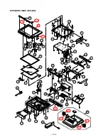
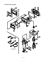
Page 127: ...A Essential B Stock recommended C Less recommended X No stock recommended MODEL QT 6000 EX 820 QT 6000 EXPLODED VIEW QT 6000 126 1 MAIN PCB BLOCK 127 2 LCD BLOCK 130 3 FRONT CASE BLOCK 130 4 REAR CASE BLOCK 131 5 POWER SUPPLY PCB BLOCK 131 6 CONNECTOR PCB BLOCK 131 7 LED PCB BLOCK 131 8 OTHER 131 QT 6060D EXPLODED VIEW QT 6060D 133 9 DISPLAY PCB BLOCK 134 10 DISPLAY BLOCK 135 11 STAND BLOCK 135 12...

Page 128: ... VIEW QT 6000 10 2 48 2 48 2 48 1 48 1 49 47 43 39 39 1 50 30 36 41 48 38 37 23 36 25 20 28 21 18 35 22 40 19 25 24 30 6 29 45 33 44 46 34 31 27 26 32 5 29 1 3 3 2 17 10 14 10 3 10 1 42 11 12 16 13 26 27 15 32 8 9 7 ...

Page 129: ... SN74LVC138APWR 1 1 1 C IC25 1000 4414 IC CMOS SN74LV74APWR 1 1 1 AC C IC16 21 50 51 1000 5662 IC CMOS SN74LV374APWR 4 4 4 AF C IC48 52 54 1000 4413 IC CMOS SN74LV32APWR 4 4 4 AB C IC22 38 39 1000 5721 IC CMOS SN74LV244APWR 3 3 3 AF C IC30 1000 7179 IC CMOS SN74LV10APWR 1 1 1 AC C IC47 57 1000 5659 IC CMOS SN74LV08APWR 2 2 2 AB C IC37 1010 5417 IC CMOS SN74LV07APWR 1 1 1 AA C IC10 1012 0129 IC CMO...

Page 130: ... R119 RESISTOR CHIP CR1 16 822JV 1 1 1 X R125 RESISTOR CHIP CR1 2 5R6JV 1 1 1 X R66 68 321 322 RESISTOR CHIP CR1 16 24R9FV 4 4 4 X R283 284 RESISTOR CHIP CR1 16 49R9FV 2 2 2 X R124 RESISTOR CHIP CR1 16 6203FV 1 1 1 X RM6 7 9 12 37 38 41 RESISTOR CHIP ARRAY CRA168 000V 19 19 19 X RM46 48 51 66 67 75 RM78 79 82 85 88 RM1 3 5 8 10 11 15 16 RESISTOR CHIP ARRAY CRA168 103JV 26 26 26 X RM23 28 50 52 59 ...

Page 131: ...TA124EETL 3 3 3 X Q1 TRANSISTOR CHIP 2SJ499 TL E 1 1 1 X Q12 TRANSISTOR CHIP 2SA2018 TL 1 1 1 X Q5 TRANSISTOR CHIP 2SA2012 TD E 1 1 1 X Q4 TRANSISTOR CHIP 2SA1729S TD E 1 1 1 X L1 INDUCTOR CHIP POWER CDRH127 LDNP 220MC 1 1 1 X N X4 1016 6818 OSCILLATOR CHIP CRYSTAL MA406 25M 1 1 1 C N X2 1016 6819 OSCILLATOR CHIP CRYSTAL MA406 20M 1 1 1 C X1 CERALOCK CHIP CSTCE8M00G55 R0 1 1 1 X X5 CERALOCK CHIP C...

Page 132: ... 1 C 3 FRONT CASE BLOCK N 10 1018 3838 CASE SUB ASSY FRONT RJE501231 001V01 1 C N 10 1018 3840 CASE SUB ASSY FRONT RJE501231 002V01 1 1 C 10 1032 4536 CASE FRONT RJE501081 001V03 1 1 1 C 10 1 1018 2639 PLATE CASIO E820 RJE501249 001V01 1 1 1 C 10 2 1030 1133 COVER DALLAS RJE501089 001V02 1 1 C 10 3 1016 5819 CHASSIS NUT RJE501118 001V01 1 1 1 X N 11 1016 5817 SEAL LCD E820 RJE501104 001V01 1 1 1 C...

Page 133: ...NP 180MC 1 1 1 X N CN9 1018 3841 CONNECTOR IMSA 9610S 25F Y914 1 1 1 C N CN6 7 1016 6854 CONNECTOR S3B PH SM4 TB LF 2 2 2 C R1 RESISTOR CHIP CR1 16 1001FV 1 1 1 X R2 RESISTOR CHIP CR1 16 3481FV 1 1 1 X R11 RESISTOR CHIP CR1 16 100JV 1 1 1 X C10 CAPACITOR CHIP CERA GRM1882C1H102JA01D 1 1 1 X C4 OS CON CHIP 35SVPD22M 1 1 1 X L2 BEADS CHIP FBMH4532HM132 T 1 1 1 X R8 RESISTOR METAL OXIDE ERX1SJ1R5P 1 ...

Page 134: ...ITE S BDPT 3X8BC 2 2 2 X SCREW BIND S BDMA 3X12BC 3 3 3 X N 46 1017 0322 SCREW BIND E820 RJE501232 001V01 2 2 2 X N 47 1017 0323 COVER U E820 RJE501212 001V01 1 1 1 C N 48 1016 5805 STAND SUB ASSY RJE501177 001V01 1 1 1 C 48 1 1030 1138 HINGE E820 RJE501095 001V02 2 2 2 C 48 2 1016 5800 WASHER W CW1L 5ZC 2 2 2 C N 49 1016 5799 COVER IBUTTON RJE501117 001V01 1 1 1 C 1002 9671 SCREW DL POSITION E475...

Page 135: ... 133 EXPLODED VIEW QT 6060D 2 11 17 14 15 20 Sales Option 16 5 6 12 13 18 19 8 7 10 3 1 4 9 5 ...

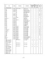
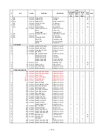
Page 136: ...TOR CHIP MCR03EZPJ560 4 X R5 RESISTOR CHIP MCR03EZPJ563 1 X R54 57 RESISTOR CHIP MCR03EZPJ684 2 X R20 71 RESISTOR CHIP MCR03EZPJ750 2 X R51 RESISTOR CHIP MCR03EZPF2403 1 X R50 RESISTOR CHIP MCR03EZPF5602 1 X R53 RESISTOR CHIP MCR03EZPF8453 1 X R49 RESISTOR CHIP MCR03EZPF9101 1 X RM3 5 7 9 12 14 RESISTOR CHIP ARRAY MNR14E0ABJ103 7 X RM1 2 4 6 8 10 11 RESISTOR CHIP ARRAY MNR14E0ABJ470 7 X N TH1 1013...

Page 137: ...E500340 002V01 1 C 3 STAND BLOCK N 1 1 1016 6709 STAND EDP RJE501141 001V01 1 C N 1 2 1016 6710 POLE EDP RJE501142 001V01 1 C N 1 3 1016 6712 SHAFT ROTARY RJE501144 001V01 1 C N 1 4 1016 6711 CAP HINGE EDP RJE501143 001V01 1 C N 1 5 1016 8769 CHASSIS EDP RJE501123 001V01 1 C N 1 6 1016 8770 CABLE SUB ASSY CNB2 RJE501196 001V01 1 C 1 7 6246 6529 RUBBER PAT ED14 E412136 1 4 AD C SCREW S BDB0 3X8NI 8...

Page 138: ... 136 12 DRAWER DL 2785 16 13 18 19 20 21 14 9 6 26 27 11 4 2 25 17 15 13 10 12 20 22 24 8 5 11 7 3 23 1 ...

Page 139: ... 3 3 X 12 1007 8903 DRAWER SUB ASSY E341274 1 1 BJ X 13 5500 0619 ROLLER DELRIN DR 19B1 2 AG B 14 5200 0106 RIVET 5X30 1 AA X 15 6246 5030 SPRING EARTH E412092 1 1 AA X 16 1007 9060 LOCK CYLINDER CL 16 1 BA C N 17 1012 1046 PANEL FRONT RJE500530 001 1 X SCREW 3X10 NI 2 X WASHER 6X13X1 0 ZMC 3 2 X 18 1007 8757 CASE BILL E140505 1 1 AT C N 19 1011 0333 CASE COIN RJE500217 001 1 C N 20 1011 0332 PLAT...

Page 140: ... 138 13 DRAWER DL 2786 13 18 19 20 21 14 4 15 13 12 20 22 24 23 25 16 17 2 3 1 9 6 26 27 11 10 8 5 11 7 ...

Page 141: ...001 4 AB X SCREW 4X5 ZMC 3 3 X 12 1007 8903 DRAWER SUB ASSY E341274 1 1 BJ X 13 5500 0619 ROLLER DELRIN DR 19B1 2 AG B 14 5200 0106 RIVET 5X30 1 AA X 15 6246 5030 SPRING EARTH E412092 1 1 AA X 16 1007 9060 LOCK CYLINDER CL 16 1 BA C N 17 1012 1046 PANEL FRONT RJE500530 001 1 X SCREW 3X10 NI 2 X 5440 0399 WASHER 6X13X1 0 ZMC 3 2 AA X 18 1007 8757 CASE BILL E140505 1 1 AT C N 19 1011 0333 CASE COIN ...

Page 142: ... 140 14 DRAWER DL 2920 9 6 11 10 8 5 11 7 2 1 3 25 26 16 24 4 14 17 15 13 12 13 18 22 21 23 19 20 20 ...

Page 143: ...05 001 4 AB X SCREW 4X5 ZMC 3 3 X 12 1007 8903 DRAWER SUB ASSY E341274 1 1 BJ X 13 5500 0619 ROLLER DELRIN DR 19B1 2 AG B 14 5200 0106 RIVET 5X30 1 AA X 15 6246 5030 SPRING EARTH E412092 1 1 AA X 16 1007 9060 LOCK CYLINDER CL 16 1 BA C N 17 1012 1046 PANEL FRONT RJE500530 001 1 X SCREW 3X10 NI 2 X 5440 0399 WASHER 6X13X1 0 ZMC 3 2 AA X 18 1007 8757 CASE BILL E140505 1 1 AT C N 19 1011 0333 CASE CO...

Page 144: ... 142 16 13 18 19 20 14 24 17 15 13 12 20 23 22 21 2 3 1 9 6 25 26 11 10 8 5 11 7 4 15 DRAWER DL 2921 ...

Page 145: ...008 0450 RUBBER DUMPER RJE500005 001 4 AB X SCREW 4X5 ZMC 3 3 X 12 1007 8903 DRAWER SUB ASSY E341274 1 1 BJ X 13 5500 0619 ROLLER DELRIN DR 19B1 2 AG B 14 5200 0106 RIVET 5X30 1 AA X 15 6246 5030 SPRING EARTH E412092 1 1 AA X 16 1007 9060 LOCK CYLINDER CL 16 1 BA C N 17 1012 1046 PANEL FRONT RJE500530 001 1 X SCREW 3X10 NI 2 X 5440 0399 WASHER 6X13X1 0 ZMC 3 2 AA X 18 1007 8757 CASE BILL E140505 1...

Page 146: ... 144 16 DRAWER DL 2425 13 18 19 20 14 15 13 12 24 23 25 4 21 16 17 2 3 1 9 6 26 27 11 10 8 5 11 7 22 ...

Page 147: ...01 4 AB X SCREW 4X5 ZMC 3 3 X 12 1007 8903 DRAWER SUB ASSY E341274 1 1 BJ X 13 5500 0619 ROLLER DELRIN DR 19B1 2 AG B 14 5200 0106 RIVET 5X30 1 AA X 15 6246 5030 SPRING EARTH E412092 1 1 AA X 16 1007 9060 LOCK CYLINDER CL 16 1 BA C N 17 1012 1046 PANEL FRONT RJE500530 001 1 X SCREW 3X10 NI 2 X 5440 0399 WASHER 6X13X1 0 ZMC 3 2 AA X 18 1007 8757 CASE BILL E140505 1 1 AT C N 19 1010 6267 CASE COIN R...

Page 148: ... 146 17 DRAWER DL 2525 13 18 19 20 14 15 13 12 24 23 25 4 21 22 16 17 2 3 1 9 6 26 27 11 10 8 5 11 7 ...

Page 149: ...01 4 AB X SCREW 4X5 ZMC 3 3 X 12 1007 8903 DRAWER SUB ASSY E341274 1 1 BJ X 13 5500 0619 ROLLER DELRIN DR 19B1 2 AG B 14 5200 0106 RIVET 5X30 1 AA X 15 6246 5030 SPRING EARTH E412092 1 1 AA X 16 1007 9060 LOCK CYLINDER CL 16 1 BA C N 17 1012 1046 PANEL FRONT RJE500530 001 1 X SCREW 3X10 NI 2 X 5440 0399 WASHER 6X13X1 0 ZMC 3 2 AA X 18 1007 8757 CASE BILL E140505 1 1 AT C N 19 1010 6267 CASE COIN R...

Page 150: ... 148 18 DRAWER DL 3616 ...

Page 151: ...24 1902 7027 KEY CYLINDER ZD00226 1 BB C 25 1907 7928 CLIP ZD00226 2 1 AJ X 26 1906 0685 CASE BILL ZD04851 1 BO C 27 1907 7926 CASE COIN ZD04843PS 1 BN C 28 1907 7925 PLATE BILL PARTITION ZD04842 4 AH C 29 1907 7924 PLATE COIN PARTITION ZD04844 5 AD C 30 1907 7923 HOLDER PARTITION PLATE ZD04845 5 AC X 31 1902 6991 PLATE BILL HOLDER FIXING ZD00245 1 AK X 32 9487 0385 STOPPER BILL HOLDER ZV27041 1 5...

Page 152: ... 150 19 DRAWER DL 3617 ...

Page 153: ... 23 1906 0684 SCREW TAPPING M3 5X8 2 AA X 24 1902 7027 KEY CYLINDER ZD00226 1 BB C 25 1907 7928 CLIP ZD00226 2 1 AJ X 26 1906 0685 CASE BILL ZD04851 1 BO C 27 1907 7926 CASE COIN ZD04843PS 1 BN C 28 1907 7925 PLATE BILL PARTITION ZD04842 4 AH C 29 1907 7924 PLATE COIN PARTITION ZD04844 5 AD C 30 1907 7923 HOLDER PARTITION PLATE ZD04845 5 AC X 31 1902 6991 PLATE BILL HOLDER FIXING ZD00245 1 AK X 32...

Page 154: ...tion of the names of items in 6 IN LINE ON LINE page 27 Correction of 7 4 Status Display page 30 Correction of 7 6 Operation of each test pages 33 34 38 43 45 Replacement of the parts list pages 127 to 132 134 135 Ver 2 Oct 2004 Correction of 5 1 Installing the display set for customer page 22 Addition of a Note in 18 Ethernet test of 7 DIAGNOSTIC OPERATION page 43 Correction of 19 MAC Address SET...

Reviews: