— 12 —
3. DATA COMMUNICATIONS
You can transfer data between two CASIO SF-5590SY,SF-5790SY, or SF-5990SY units, or between
your Digital Diary and a personal computer only. You cannot exchange data with any other CASIO
Digital Diary model. Data communications can be performed while in the Telephone Directory, Memo,
Schedule Keeper, Calendar, To Do, Reminder, or Expense Manager Mode.
Data synchronizing helps you to make sure that the data in your PC and your Digital Diary are always
up to date.
■
Setting Up for Data Communications
The following describes what you would do to set up for data communications between two Digital
Diary units or between a Digital Diary unit and a personal computer.
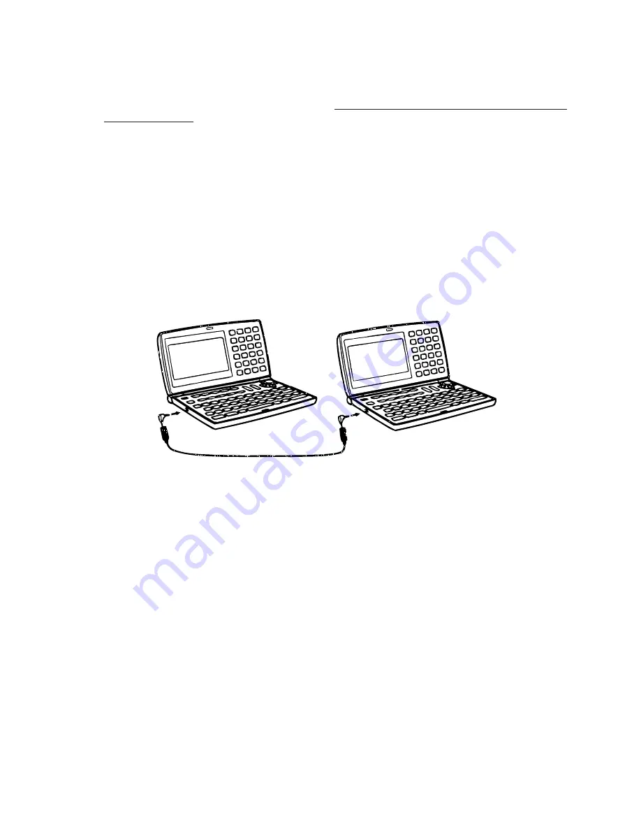
To connect to another Digital Diary unit
1. Make sure that the power of both units is turned off.
2. Open the covers of the data communications jacks of the two Digital Diary units.
3. Connect the two units using the SB-63 cable.
Important!
• Be sure to close the connector covers of the Digital Diary units when you are not perfoming data
communications.
Performing data communications between a Digital Diary unit and a personal computer run-
ning Windows 3.1 or Windows 95
See the manual that comes with the FA-128 for details on connecting to a computer and setting up for
communication.
Note
• The CASIO Data Communication Package may not be included with certain Digital Diary models.
Please note that there are a number of different CASIO Data Communication Packages to suit
various computers and Digital Diary types. Because of this, you should note the following impor-
tant points when purchasing a Data Communication Package. If you have any question about
which package you need, consult with experts.
• Make sure the Data Communication Package is designed for you with your particular model of
personal computer.
• For information on how to connect the Digital Diary to a personal computer, see the user’s manual
that comes with the Data Communication Package.
Summary of Contents for SF-5590SY
Page 19: ... 19 6 SCHEMATIC DIAGRAMS 6 1 MAIN PCB ASS Y A342054 1 4 CPU ...
Page 20: ... 20 6 1 MAIN PCB ASS Y A342054 2 4 ...
Page 21: ... 21 6 1 MAIN PCB ASS Y A342054 3 4 ...
Page 22: ... 22 6 1 MAIN PCB ASS Y A342054 4 4 ...
Page 23: ... 23 6 2 KEYBOARD PCB ASS Y A342055 1 3 COM PORT BUZZER ...
Page 24: ... 24 POWER SUPPLY 6 2 KEYBOARD PCB ASS Y A342055 2 3 ...
Page 25: ... 25 6 2 KEYBOARD PCB ASS Y A342055 3 3 ...
Page 33: ...MA0900571A ...


