background image

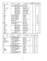
DL-2779(M type) UK, Germany, Other countries

N

Item

Code No.

Parts Name

Specification

Qt'y

Price

Rank

code

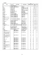
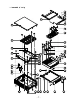
1. MAIN CASE BLOCK

N

1

10078897

CASE/MAIN

E140494-1

1

BS

X

2

55000619

ROLLER/DELRIN

DR-19B1

2

AG

B

N

3

10079066

NUT

6 ZMC-3

2

AA

X

N

4

10078764

LEVER/HOOK

E341286-1

1

AA

C

N

5

10078754

AXIS/HOOK LEVER

E341241-1

1

AA

C

N

SCREW

3X8 ZMC-3

4

AA

X

6

10080393

SPRING/LOCK

RJE500007-001

1

AA

X

7

62465010

SPRING/PRESS

E412069-1

1

AA

X

8

62466529

RUBBER/PAD

E412136-1

4

AD

X

N

9

10078894

SOLENOIDO SUB ASSY

E341301*2

1

BD

B

N

10

10078901

COVER/UPPER

E140498-1

1

AN

X

N

11

10078759

RAIL/MLED18

E240841-1

1

AQ

C

N

12

10078760

RAIL/MRED18

E240842-1

1

AQ

C

13

10080450

RUBBER/DUMPER

RJE500005-001

4

AB

X

N

SCREW

4X10 ZMC-3

6

X

N

14

10079068

WASHER   

6X13X1.0 ZMC-3

2

AA

X

N

15

10078883

COVER/TOP

E240849-1

1

BZ

X

N

SCREW

3X8 NI

3

X

10078890

LABEL/DL-2779

E341256-10

1

AA

X

16

30007231

SWITCH/MICRO

V-103-1A5

1

BE

B

N

17

54400225

SCREW

3X16 ZMC-3

1

AA

X

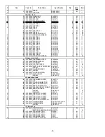
2. UPPER DRAWER

N

18

10078740

PLATE/STP

E441288-1

1

AA

C

N

19

10078741

LEVER/STP

E341242-1

1

AA

C

N

20

10078755

HOLDER/STP

E341243-1

1

AA

C

N

21

10078898

DRAWER/UPPER

E140495-1

1

AT

C

N

22

10078899

PANEL/FRONT

E140496-1

1

AP

X

SCREW

3X8 ZMC-3

2

AA

X

SCREW

3X10 NI

2

AA

X

3. LOWER DRAWER

N

23

10078903

DRAWER SUB ASSY/LOWER

E341274*1

1

BJ

X

24

55000619

ROLLER/DERULIN

DR-19B1

2

AG

B

25

52000106

RIVET

5X30

1

AA

X

N

26

62465030

SPRING/EARTH

E412092-1

1

AA

X

N

27

10079060

LOCK/CYLINDER

CL-16

1

BA

C

N

28

10078900

PANEL/FRONT

E140497-1

1

AV

X

N

SCREW

3X10 NI

2

AA

X

N

29

54400399

WASHER

6X13X1.0 ZMC-3

2

AA

X

N

30

10078757

CASE/BILL

E140505-1

1

AT

C

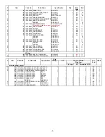
31

62473935

CASE/COIN

E140058-1

1

AX

C

N

32

10079062

BILL HOLDER SUB ASSY

E341290*1

4

AE

B

N

33

10079063

SPRING/BILL HOLDER

E441357-1

4

AA

C

N

34

10079064

BRACKET/BILL HOLDER

E240845-1

1

AD

X

35

10051420

PLATE/COIN CASE PARTITION

E340173A-1

6

AC

C

36

62214911

PLATE/BILL CASE PARTITION

ZD43652

3

AC

C

SCREW

3X8 ZMC-3

3

AA

X

SCREW

3X5 NI

4

AA

X

- 55 -

Summary of Contents for TE-100

Page 1: ...SERVICE MANUAL without price ELECTRONIC CASH REGISTER TE 2000 EX 273 MAR 2002 ...

Page 2: ...E 1 SPECIFICATIONS 1 2 INITILAIZE OPERATION 3 3 BLOCK DIAGRAM 4 4 DISASSEMBLY 5 5 CIRCUIT EXPLANATIONS 16 6 DIAGNOSTIC OPERATION 21 7 ERROR CODE LIST 28 8 IC DATA 29 9 PCB LAYOUT 30 10 CIRCUIT DIAGRAMS 32 11 PARTS LIST 45 ...

Page 3: ...es x 8bits Flash ROM Name LE28F4001CTS 12C03 Capacity 4 Mbits 512Kbytes x 8bits DRAWER NAME Type DL 2778 M D 18D2C B84RM 13 Europe Other countries DL 2779 M D 18D2C B84RM 13 UK Germany Specification Note Power consumption 120V 220V 230V 240V In operationMax 0 65A 0 35A 0 35A 0 35A Stand by Max 0 3A 0 2A 0 2A 0 2A Memory protection Back up battery Mangan battery R6 UM 3 Back up period 1 year 25 C B...

Page 4: ...nsgefahr bei unsachgemäßem Austausch der Batterie Ersatz nur durch denselben oder einen vom Hersteller empfohlenen gleichwertigen Typ Entsorgung gebrauchter Batterien nach Angaben des Herstellers ADVARSEL Lithiumbatteri Eksplosionsfare ved fejlagtig hándtering Udskiftning má kun ske med batteri af samme fabrikat og type Levér det brugte batteri tilbage til leverandØren DEVICE NAME MODEL NOTE PC ca...

Page 5: ... time 00000000 appears on the display and the printer operates for a few seconds Initialization is complete when the printer stops operating To select the monetary system and date format Use the following procedure to specify the number of monetary decimal places the date format This setting should be performed immediately after you initialize the cash register Initializing the cash register Autom...

Page 6: ...in 28 pin 28 pin 4 pin 3 pin 9 pin 30 pin 30 pin 3 pin COM E272 PR E272 PR Printer 30 pin 30 pin DRW 3 pin 28 pin 28 pin E272 E2 1 E272 1 8 pin 12 pin Pop up Display Character Display Main Display E272 E2 2 Winder Motor POWER MODE SW KEY BOARD BATT Stroke Key ...

Page 7: ...2 1Remove one screw 2Slide the DISPLAY PANEL in the direction of the arrow and remove the hook 3Slide the DISPLAY PANEL and lift it up 4Remove two FPCs CN103 CN104 4Remove the DISPLAY UNIT 1 2 3 4 5 4 DISASSEMBLY 2 1 CN103 CN104 Screw Hook Hook ...

Page 8: ...NIT to front side and lift it up Then remove one FPC CN13 1 2 3 PRINTER UNIT 1 Remove the upper cover as shown in steps 1 to 3 of page 5 2 Remove the pully 3 Lift up the printer unit cover as Fig 4 Remove the battery cover CN13 Fig Screws 1 2 ...

Page 9: ... four screws and two connectors CN9 CN10 7 Removing the PRINTER UNIT 1 Remove five screws 2 Remove the joint PCB 3 Remove the PRINTER UNIT while pressing two hooks as shown in the figure Hook opposite side 1 3 Screws Screws CN10 CN9 2 ...

Page 10: ...PPLY UNIT 1 Remove the upper cover as shown in steps 1 to 3 of page 5 2 Remove two FPCs CN101 102 3 Remove two screws 4 Remove the Main display with the upper case of the Power supply 5 Remove one connector CN5 and three screws and then the power unit Screws CN102 CN101 Hooks CN5 Screws F1 Voltage selector switch Nomally Do not change the voltage position ...

Page 11: ... to 3 of page 5 2 Remove two screws and eight connectors CN3 CN10 and then the MAIN PCB CN7 CN6 CN5 CN8 CN10 CN9 CN3 CN4 Screws Removing the Drawer 1 Remove the Upper cover Printer unit and Power supply 2 Remove the Drawer from the ECR 6 Remove the core Core ...

Page 12: ...lower drawer 3 Remove the top cover 1 Push the lever in the direction of the arrow and pull out the lower tray 2 Pull up the drawer 2 Remove the top cover by sliding it in the direction of the arrow 1 Turn the drawer upside down and then remove three screws as fig ...

Page 13: ...1Remove two screws and then the SOLENOID 2Remove the SPRING 3Remove the hook lever by removing its stopper from the bottom surface 1 Remove two screws 2 Open the case to some extent and remove the UPPER COVER by lifting it up Screws ...

Page 14: ... 12 6 Remove the screw and the roller X 2 ...

Page 15: ... direction of the arrow and pull out the lower tray 2 Remove the COIN CASE 3 Remove the BILL CASE 4 Remove the tray 2 Remove the upper iron plate 1 Pull out the upper tray 2 Remove three screws 3 Remove the top cover by sliding it in the direction of the arrow 2 3 4 Screws ...

Page 16: ... COVER 1 Remove four screws 2 Open the case to some extent and remove the UPPER COVER by lifting it up 4 Remove the upper tray 5 Remove four screws and then RAIL MLED X 2 6 Remove the screw and the roller Screws Screw Screws ...

Page 17: ... 15 7 Remove the UPPER COVER 1 Remove two screws and the SOLENOID 2 Remove the SPRING Screws ...

Page 18: ...n No 2 VCC DC5V For the logic circuit power Output Pin No 3 VP DC8V For the printer Output Pin No 4 GND Voltage selector switch PS 272 U Normally Do not change the voltage position 230V SJW3 SJW1 SW1 JW4 JW1 R2 F1 T4A 250V R1 115V SJW2 JW3 AC2 AC1 PT1 C10 C11 CN1 C3 C2 L2 L4 L1 R3 D3 D2 IC1 IC2 C7 C8 C4 C9 C5 C6 C1 D1 BLACK PRI SEC BLK GND 8V 5V 10V RED 1 7 17 8 L3 R4 F1 4A 250V ...

Page 19: ... AD0 59 J_PE IN Pepar end signal TE 2000 only 20 AD1 I O DATA BUS AD1 60 RESET IN RESET signal 21 AD2 I O DATA BUS AD2 61 H_UP R IN H UP signal for Printer 22 AD3 I O DATA BUS AD3 62 H_UP J I O H UP signal for Printer TE 2000 only 23 AD4 I O DATA BUS AD4 63 MT_IRQ I O MT_IRQ from GATE Array 24 AD5 I O DATA BUS AD5 64 PWD I O Power supply status signal 25 AD6 I O DATA BUS AD6 65 MD_OFF I O OFF from...

Page 20: ...Vss 23 ASTB I ASTB from CPU 73 RAM1_CE O Chip enable for RAM1 24 RAM_Dis I Chip select for RAM 74 RAM2_CE O Chip enable for RAM2 25 A15 I ADDRESS A15 75 FIS_CE O Chip enable for FIS ROM 26 A14 I ADDRESS A14 76 STP_CE O Chip enable for RAM 27 A13 I ADDRESS A13 77 FLH_CE O Chip enable for FLASH ROM 28 A12 I ADDRESS A12 78 Vcc VCC 29 A11 I ADDRESS A11 79 GND Vss 30 A10 I ADDRESS A10 80 GND Vss 31 A9 ...

Page 21: ... Not used 115 C108 O to 14 seg LED 145 Vcc O VCC 116 C109 O to 14 seg LED 146 SCK O CP1 terminal 117 C110 O to 14 seg LED 147 AMC O CP2 terminal 118 C111 O to 14 seg LED 148 GND Vss 119 C112 O to 14 seg LED 149 MTR_1J O MTR_J1 by Printer circuit 120 Vcc VDD 150 MTR_2J O MTR_J2 by Printer circuit 121 GND Vss 151 MTR_3J O MTR_J3 by Printer circuit 122 GND Vss 152 MTR_4J O MTR_J4 by Printer circuit 1...

Page 22: ...The COM1 circuit is as follows 5 7 BATTERY CIRCUIT The following shows the low battery indicator The BATTERY circuit is as follows Japan only Japan only Note This message is a appeared when the battery became 3 or less volts ...

Page 23: ... in the test mode a Displaying hard key codes except ten keys clear and FEED buttons b Displaying the conditions of various switches change of conditions of various switches pressing clear button c Display Print Drawer test numeric of 1 through 3 digits 2 SUB TOTAL Displaying hard key codes Pressing switches other than ten keys clear and FEED buttons displays the hard key codes as shown below 2000...

Page 24: ...only 1 OPEN 0 SHORT PAD2 Language 1 OPEN English 0 SHORT German Paper END sensor 0 With paper 1 No receipt paper 2 No journal paper only TE 2000 3 No receipt and journal paper only TE 2000 Drawer sensor 1 open HIGH 0 closed Low 0 is displayed without the sensor Displaying modes PGM 1 RF 2 REG 3 CAL 4 X 5 Z 6 No contact 0 TE 100 TK T200 TE 2000 B Euope D UK G Germany BU Other PAD2 OPEN OPEN SHORT O...

Page 25: ... segments commas and transactions are lit 2 ROM CHECK Confirm that the ROM CHECK SUM the least significant digit is 00H 3 RAM READ WRITE TEST Perform READ WRITE TEST within the designated capacity of RAM with printing 4 Drawer open Open the drawer 5 Test print Perform printing test as below 6 Time and date setting Set the time and date to 23 59 on December 31 2002 7 Issuing receipt Issuing receipt...

Page 26: ...ess Consecutive printing at a certain interval Operation Y X 2 2 SUBTOTAL X 0 or abbreviated The following is printed 45 times a minute 1 The following is printed 25 times the drawer is opened 5 times and receipt is issued 5 times a minute Y 0 or abbreviated Normally no input 1 No waiting time between printing therefore consecutive printing is performed Printing stops by such causes as power failu...

Page 27: ...rformed up to the last address in RAM the receipt is issued and the test is ended 1 The test is performed consecutively until power failure or OFF mode is lit during this test Display format x x x Bank No Plint format Issuing receipt Displaying BACK UP BATTERY voltage A D convert The value calcuated based on the VCC of CPU 4 00V is displayed Before this test make sure to perform all tests 1 2 The ...

Page 28: ...he most significant digit which is displayed during the test When the test normally ends the following is printed and the receipt is issued Issuing receipt When the test does not end normally the following is printed and the receipt is issued X Error code Issuing receipt 0 Time over 1 Overrun 2 Flaming error 3 RxD line data error 4 DSR line reception error Printing all characters Operation X 8 2 S...

Page 29: ...Time is displayed 1 The time 23 hours 59 minutes and 50 seconds is set This operation continue the time display until the input of the clear button or power failure Print image 2 3 5 9 5 0 Ending the TEST mode To end the TEST mode perform INITIALIZE remove the battery ...

Page 30: ...paper end Receipt paper end Transaction cancel buffer full Finalization of a transaction attempted without confirming the subtotal Finalize operation attempted without entering amount tender Change amount exceeds preset limit Read reset operation without declaring cash in drawer This error appears only when this function is activated Action Retum the mode switch to its original setting and finaliz...

Page 31: ... IN1 14 13 12 11 OUT3 OUT4 GND GND IN4 5 6 7 IN1 IN2 IN IN Q1 Q2 Q3 Q4 Q6 Q5 Q7 Q8 IN2 10 9 8 IN4 IN3 IN3 1ch 3ch 2ch 4ch 2 BA10393F E2 IC7 3 HIN202CBN IC5 1 1ch 2 3 4 OUT1 IN1 IN1 VEE 8 7 6 5 VCC OUT2 IN2 IN2 2ch 4 UMA0206 UN206 IC1 2 3 4 7 8 9 10 1 2 3 4 5 6 ...

Page 32: ...7 Q27Q25 Q26 Q24 R24 R38 R49 R48 D23 R19 R137 R136 R16 Q23 R34 R35 R36 R39 R40 R159 R21 R20 RM4 RM5 RM6 RM3 D22 R37 Q38 Q18 Q19 Q16 Q17 R33 Q21 Q22 Q20 R23 R22 Q1 A A C R1 R145 C2 D13 D14 D15 D16 Q14 Q15 D19 FU1 C5 C4 C6 R18 Q12 R3 D17 C IC9 R149 R50 R51 D26 D25 160 CP1 CP3 CP2 RM13 RM15 RM11 RM20 RM21 RM22 RM23 RM8 RM19 RM18RM17 R141 R142 RM12 RM14 CM8 CM9 CM10 CM11 CM12 CM13 CM14 CM15 CP4 CP5 CP...

Page 33: ... R75 R87 C22 R84 C20 R74 R72 R82 R79 C21 R73 R71 C53 C61 C59 C50 C50 C58 C51 TP7 TP6 TP1 TP5 TP4 TP2 TP3 R17 R68 R69 R70 C10 C11 C19 C33 C35 C49 R157 C34 R139 C47 C48 R140 R156 R155 C44 C36 C37 C46 C45 C56 C55 C54 TP9 TP8 R158 R120 C38 R119 C39 R121 R130 C41 C42 C43 R131 R132 R133 R134 R135 R122 R123 R124 R125 R126 R127 R128 R129 R144 TP11 1 2 3 4 5 C32 C40 R138 TP10 R148 A B C D E F 1 2 3 4 5 6 R...

Page 34: ...GRAM 33 2 MAIN PCB CIRCUIT 34 2 1 MAIN PCB CIRCUIT 1 4 34 2 2 MAIN PCB CIRCUIT 2 4 35 2 3 MAIN PCB CIRCUIT 3 4 36 2 4 MAIN PCB CIRCUIT 4 4 37 3 MAIN DISPLAY 38 4 POP_UP DISPLAY 39 5 PRINTER CONNECTOR BOARD 40 6 KEY BOARD 41 7 POWER SUPPLY CIRCUIT 42 8 BATTERY 43 9 MOTOR 44 ...

Page 35: ...Model TE 2000 Name Board No Drawing No CASIO COMPUTER CO LTD 33 LOCATION OF PRINTED CIRCUIT BOARDS EX 273 RJE500052D301 ...

Page 36: ...Model TE 2000 Name Board No Drawing No CASIO COMPUTER CO LTD 34 MAIN CIRCUIT 1 4 Japan only Japan only Japan only Japan only E273 1 RJE500055D201 ...

Page 37: ...Model TE 2000 Name Board No Drawing No CASIO COMPUTER CO LTD 35 MAIN CIRCUIT 2 4 E273 1 RJE500055D201 ...

Page 38: ...Model TE 2000 Name Board No Drawing No CASIO COMPUTER CO LTD 36 For EX 273 TE 2000 only MAIN CIRCUIT 3 4 E273 1 RJE500055D201 ...

Page 39: ...Model TE 2000 Name Board No Drawing No CASIO COMPUTER CO LTD 37 MAIN CIRCUIT 4 4 E273 1 RJE500055D201 ...

Page 40: ...Model TE 2000 Name Board No Drawing No CASIO COMPUTER CO LTD 38 MAIN DISPLAY E273 E2 1 RJE500056D301 ...

Page 41: ...Model TE 2000 Name Board No Drawing No CASIO COMPUTER CO LTD 39 POP_UP DISPLAY E273 E2 2 RJE500057D301 ...

Page 42: ...Model TE 2000 Name Board No Drawing No CASIO COMPUTER CO LTD 40 PRINTER CONNECTOR BOARD E273 PR RJE500058D301 ...

Page 43: ...Model TE 2000 Name Board No Drawing No CASIO COMPUTER CO LTD 41 KEY BOARD RJE500059D301 ...

Page 44: ...Model TE 2000 Name Board No Drawing No CASIO COMPUTER CO LTD 42 POWER SUPPLY CIRCUIT Europe UK Germany Other RJE500060D301 ...

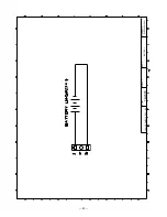
Page 45: ...Model TE 2000 Name Board No Drawing No CASIO COMPUTER CO LTD 43 BATTERY RJE500061D401 ...

Page 46: ...Model TE 2000 Name Board No Drawing No CASIO COMPUTER CO LTD 44 MOTER RJE500062D401 ...

Page 47: ... not supply the spare parts without parts code 5 Remarks Q ty Quantity used per unit RANK A Essential B Stock recommended C Less recommended X No stock recommended 11 PARTS LIST PARTS LIST MODEL TE 2000 EX 273 CONTENTS Explode view 46 1 MAIN PCB BLOCK 48 2 MAIN DISPLAY PCB BLOCK 49 3 CUSTOMER DISPLAY BLOCK 49 4 BUTTON BLOCK 50 5 UPPER CASE BLOCK 50 6 LOWER CASE BLOCK 50 7 PRINTER BLOCK 50 8 OTHERS...

Page 48: ...1 90 87 1 53 56 55 4 53 86 52 46 66 70 75 77 71 71 60 62 61 82 58 57 79 59 65 64 71 71 63 5 6 40 88 78 67 68 74 76 38 85 73 72 73 72 39 42 41 43 2 3 48 44 49 83 52 7 91 8 36 47 89 92 54 45 80 84 69 51 50 50 51 ...

Page 49: ... 47 17 18 20 18 16 20 19 15 15 21 21 22 22 21 21 17 23 34 23 34 16 19 14 11 12 22 15 21 10 13 35 ...

Page 50: ...B N RM3 5 12 14 27975518 RESISTOR CHIP NETWORKRAC1608 1014DJT 2 2 AA B RM1 2 4 6 11 13 15 26601156 RESISTOR CHIP NETWORKRAC1608 1034DJT 16 16 AA B 19 23 L1 30132359 INDUCTOR BK3216 4S601 T 1 1 AA B L2 3 30008056 INDUCTOR FBMH3216HM501NT 2 2 AB B X2 25203445 CRYSTAL C 002RX M90 76 1 1 AD B N X1 10077190 CRYSTAL CERAMIC CSTCC5M00G53 R0 1 1 AD B N SP1 10079249 BUZZER PKM22EPT 2001 B0 1 1 AG C R133 RE...

Page 51: ... CHIP RC1608 203 J T 2 2 X R135 RESISTOR CHIP RC1608 103 F T 1 1 X R65 RESISTOR CHIP RC1608 2491 F T 1 1 X R66 RESISTOR CHIP RC1608 152 F T 1 1 X C64 65 CAPACITOR CHIP UMK107CH471JZ T 2 2 X C62 63 66 CAPACITOR CHIP UMK107CH221JZ T 3 3 X CM17 18 10080318 CAPACITOR MODULE MNA142C102MK 2 2 AB B R156 157 RESISTOR CHIP RC1608 100 J T 2 2 X R136 RESISTOR CHIP RC1608 274 J T 1 1 X D29 34 27752079 DIODE D...

Page 52: ...599 PANEL DISPLAY E140469 1 1 AT C N 38 10078726 COVER MK E140464 2 1 AG C N 39 10079914 CUTTER PAPER E441364 1 1 AA B N 40 10072504 SWITCH ASSY MODE KEY E341249 1 1 AT C SCREW 3X8 ZMC 3 17 X N 41 10078725 COVER PRINTER E140467 2 1 AN C N 42 10078871 SCREW 4X70 ZMC 3 1 AA C 43 10080665 COVER JOURNAL E341236 1 1 AB C 10085287 PLATE BLIND RJE500094 1 1 AA C SCREW 3X8 ZMC 3 3 X 6 Lower case block N 4...

Page 53: ...W 3X8 ZMC 3 9 X SCREW 3X6 ZMC 3 5 X N 80 10072547 PULLY WIND E240814 1 1 AF C N 81 10079266 SPOOL PAPER E341312 1 1 AG C 82 10080666 COVER BATTERY E311096 4 1 AC C 83 10083676 CORE FERRITE RT18X6X10 1 AD C 8 Other 84 62464000 KEY SET SUB ASSY E312046 2 1 AK C N 85 10078829 NAME PLATE TE 2000 E341307 5 1 AL C Q ty N Item Code No Specification Europe UK Price Rank Code Europe UK USA 9 Power supply b...

Page 54: ... 52 10 DRAWER DL 2778 25 22 28 29 30 17 18 19 20 16 31 27 23 6 4 9 11 10 15 13 12 5 7 26 24 22 27 21 1 8 32 34 33 2 13 13 14 3 ...

Page 55: ... 10078889 LABEL DL 2778 E341256 9 1 AA X 2 UPPER DRAWER N 16 10078898 DRAWER UPPER E140495 1 1 AT C N 17 10078899 PANEL FRONT E140496 1 1 AP X N 18 10078740 PLATE STP E441288 1 1 AA C N 19 10078741 LEVER STP E341242 1 1 AA C N 20 10078755 HOLDER STP E341243 1 1 AA C SCREW 3X8 ZMC 3 2 X SCREW 3X10 NI 2 X 3 LOWER DRAWER N 21 10078903 DRAWER SUB ASSY LOWER E341274 1 1 BJ X 22 55000619 ROLLER DERULIN ...

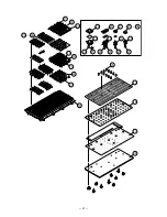
Page 56: ... 54 11 DRAWER DL 2779 27 24 30 31 35 22 18 19 20 21 36 29 25 6 4 9 11 17 10 15 13 12 5 16 7 28 26 24 29 23 1 8 32 34 33 2 13 13 14 3 ...

Page 57: ...0007231 SWITCH MICRO V 103 1A5 1 BE B N 17 54400225 SCREW 3X16 ZMC 3 1 AA X 2 UPPER DRAWER N 18 10078740 PLATE STP E441288 1 1 AA C N 19 10078741 LEVER STP E341242 1 1 AA C N 20 10078755 HOLDER STP E341243 1 1 AA C N 21 10078898 DRAWER UPPER E140495 1 1 AT C N 22 10078899 PANEL FRONT E140496 1 1 AP X SCREW 3X8 ZMC 3 2 AA X SCREW 3X10 NI 2 AA X 3 LOWER DRAWER N 23 10078903 DRAWER SUB ASSY LOWER E34...

Page 58: ...verseas Service Division Nishi Shinjuku Kimuraya Bldg 1F 5 25 Nishi Shinjuku 7 Chome Shinjuku ku Tokyo 160 0023 Japan Ver 1 Correctionofpage1 page46andpage50 Ver 2 Correctionofpage1andpage16 Ver 3 Correctionofpage23 25and51 ...

Reviews: