— 29 —
5
. DIA
G
NO
S
TIC OPERATION
5
-1. To start the dia
g
nostic pro
g
ram
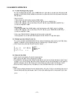
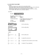
To enter the diagnostic program, press ”99990000<ST>” right after reset-and-start, IPL boot or INT
operation. In QA DIAG (factory module also) module, the mode transfers to the diagnostic mode after
INT operation.
* Reset-and-start
1
Press the reset switch while pressing JFEED button.
2
When “INT” appears in the first line of the LCD dot line, press<SUBTOTAL>.
3
When “INT” appears in the second line of the LCD dot line, press”99990000<SUBTOTAL>”.
4
Enter the diagnostic mode.
* INT operation
1
While holding down the JFEED button, align the mode key with “PGM” using the OW key.
2
When “INT” appears in the second line of the LCD dot line, press “99990000<SUBTOTAL>”.
3
Enter the diagnostic mode.
* In the case if “MASK DIAG” is displayed and the counter is activated
A false operation has led to the MASK diagnostic mode. Perform IPL operation again.
5
-2. Displayin
g
and printin
g
the version
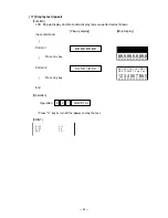
The version of DIAG and MADK ROM/IOC are printed immediately after entering the DIAG mode.
However, DIAG/IOC version printing function is available only in QA DIA module.
•
All test results are printed by the built-in printer receipt.
5
-3. Notes for the DIA
G
•
All test result are printed by the built-in receipt printer.
•
Make sure to test HHS-15 by connecting to COM2.
•
To perform the continuous check, follow the direction for each test, and input numbers except 0. Input
numbers 1-9 as the command how many times to perform the test for the operation in each page to
perform continuous check. Note that you can only choose one time check or continuous check.
•
When turn off by rotating the key, the display is unlit, and DAIG command is not accepted.
[Others]
•
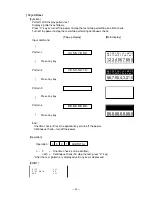
ESC value is printed as follows if the test ended by force. Press the “C” key or turn off the power to end
the test while performing continuous check. The result of ending by force is not printed in each test.
| ESC |
I o c
V e r
:
4 2 3 3
A A N Z A C
M a s k
V e r
:
4 2 0 7
A A O A A A
D i a g
V e r
:
M a y
2 5
2 0 0 5
0 9 : 5 4
IOC
MASK ROM
DIAG
Summary of Contents for TE-2200
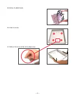
Page 16: ... 14 DRAWER 35 Remove the case 36 Remove 10 screws 37 Remove the DARWER cable ...
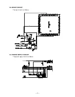
Page 22: ... 20 4 5 DRAWER I F CIRCUIT The drawer open circuit is as follows ...
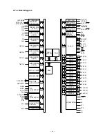
Page 23: ... 21 4 6 PRINTER CONTROL CIRCUIT The printer control circuit is as follows ...
Page 68: ... 66 8 PCB LAYOUT MAIN PCB E466 1 PCB TOP VIEW ...
Page 69: ... 67 MAIN PCB E466 1 PCB BOTTOM VIEW ...
Page 93: ... 91 TE 2400 KEYBOARD BLOCK 16 15 17 18 19 20 21 22 23 ...
Page 98: ... 96 11 DRAWER DL 2429 for USA 16 17 18 11 8 6 15 14 19 9 10 1 12 20 21 5 4 2 3 5 13 7 ...
Page 104: ... 102 14 DRAWER DL 2799 for UK Canada 12 17 11 8 7 6 9 10 1 18 19 5 4 2 5 16 13 15 14 3 ...

