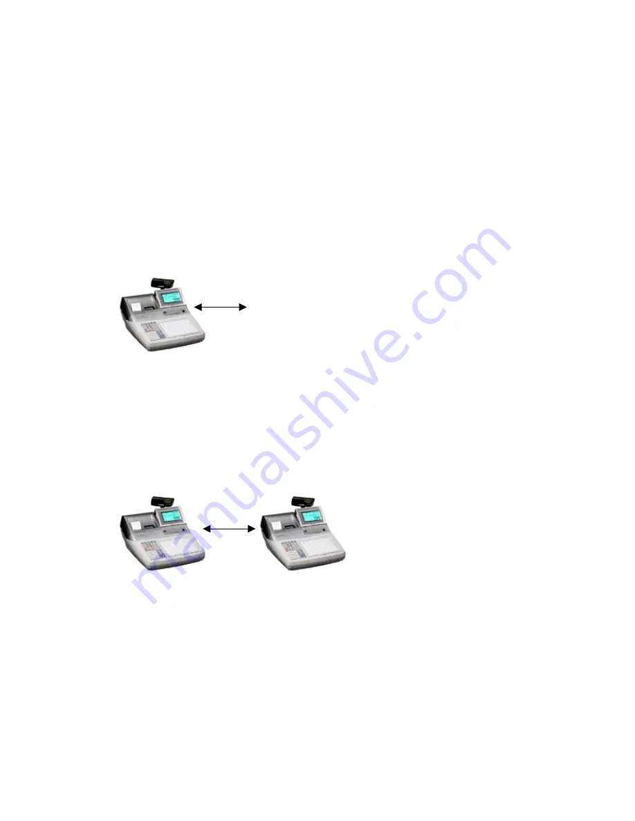
Setting up the In-Line network in detail
To set up the in-line network you must install the I/O PB-17 boards
into each terminal.
There are 2 types of In-line network selectable via a selector
switch, which can be found on the underside of the cash register
Selector switch position 1 = Casio In-Line (ARCNET)
Selector switch position 2 = Cat-5A Cable
Initialise the first terminal and the machine number will be
MC#01connect the Casio or Cat-5 cable to the white Casio
connector or the OUT port of Cat-5 board.
In-line cable
Master
Add the second cash register and plug the In-line cable into the
white Casio connector or the IN port of the Cat-5 board
Initialise the cash register and check that the terminal has been
recognised in the In-line network by checking that the MC# number
is MC#02
In-line
Master
Satellite
Add the third cash register to the network and plug the In-line
cable into the white Casio connector or the OUT port of machine 2
to the IN port of the Cat-5 board.
Initialise the cash register and check that the terminal has been
recognised in the In-line network by checking that the MC# number
is MC#03
Copy the above for machine 4 looking for MC#04 after initialisation
26
Summary of Contents for TE-4000
Page 3: ...C CH HA AP PT TE ER R 1 1 H HA AR RD DW WA AR RE E C CO ON NF FI IG GU UR RA AT TI IO ON N 3 ...
Page 5: ...5 ...
Page 6: ...6 ...
Page 13: ...How to Initialises the cash register in detail 13 ...
Page 17: ...Memory Allocation sheets System files Check files Clerk files Scanning files 17 ...
Page 18: ...Program Buffer files 18 ...
Page 20: ...Assigning Function Keys 20 ...
Page 44: ...Clock In Out function worksheet To take the time and attendance report 44 ...
Page 49: ...C CH HA AP PT TE ER R 1 12 2 C CF F C CA AR RD D O OP PT TI IO ON NS S 49 ...
Page 50: ...In Line send and receive 50 ...
Page 53: ...To allow use of magnetic Dallas keys Turn to program mode 2722 1100000000 53 ...
Page 54: ...C CH HA AP PT TE ER R 1 14 4 E ER RR RO OR R C CO OD DE ES S 54 ...
Page 55: ...55 ...


