—
— 93
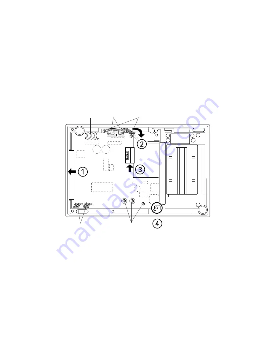
3. Disconnect 5 cables.
4. Remove 5 screws.
5. Follow the steps below; then remove the main circuit board assembly.
①
Slide the board toward the arrow
①
.
②
Move the 2 cables toward the arrow
②
.
③
Move the board toward the arrow
③
.
④
Once the board is released from the plate (marked with
④
), the main circuit board can be
removed from the printer.
Refer to the corresponding assembly sections in this chapter for assembly procedures.
connectors
connector
connectors
screws
Summary of Contents for UP-250
Page 1: ...EXTERNAL PRINTER FEB 2000 MODEL UP 250 without price TECHNICAL MANUAL ...
Page 95: ... 86 END END Yes No Action 4 Replace main PCB Replace printer OK Action 4 mechanism assembly ...
Page 136: ... 127 ...
Page 149: ... 140 Main Circuit Board Parts Layout ...
Page 150: ... 141 RS 232 Serial Interface Circuit Board Parts Layout ...
Page 151: ... 142 IEEE 1284 Parallel Interface Circuit Board Parts Layout ...
Page 152: ...RS 485 Serial Interface Circuit Board Parts Layout 143 ...
Page 160: ... 151 Case Unit Lubrication Points Diagram 4 G 31 4 G 31 3 G 31 3 G 31 ...
Page 163: ... 154 EXPLODED DIAGRAM FOR TM U200B U210B NO 1 ...
Page 164: ... 155 EXPLODED DIAGRAM FOR TM U200B U200PB U210B U210PB NO 2 ...


