—
— 118
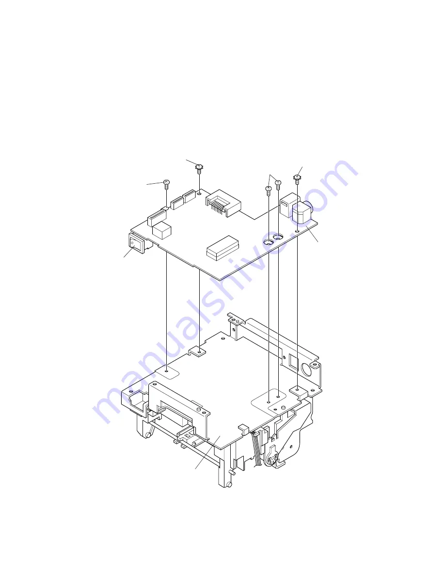
Main Assembly 3 (Case Unit)
Main circuit board assembly
1. Attach the main circuit board assembly to the upper plate by attaching the power switch
side first and then the drawer kick-out and power connectors side. Secure the circuit board
with the screws.
✔
Make sure to use the correct screw for each location.
CP(0)(M3x6)
[0.59 to 0.78 N • m
(6 to 8 kgf • cm)]
CPS-tite (M3x6)
Main circuit
board assembly
CP(0) (M3x6)
[0.59 to 0.78 N • m
(6 to 8 kgf • cm)]
CPS-tite (M3x6)
[0.59 to 0.78 N • m
(6 to 8 kgf • cm)]
Power switch
Upper plate
Summary of Contents for UP-250
Page 1: ...EXTERNAL PRINTER FEB 2000 MODEL UP 250 without price TECHNICAL MANUAL ...
Page 95: ... 86 END END Yes No Action 4 Replace main PCB Replace printer OK Action 4 mechanism assembly ...
Page 136: ... 127 ...
Page 149: ... 140 Main Circuit Board Parts Layout ...
Page 150: ... 141 RS 232 Serial Interface Circuit Board Parts Layout ...
Page 151: ... 142 IEEE 1284 Parallel Interface Circuit Board Parts Layout ...
Page 152: ...RS 485 Serial Interface Circuit Board Parts Layout 143 ...
Page 160: ... 151 Case Unit Lubrication Points Diagram 4 G 31 4 G 31 3 G 31 3 G 31 ...
Page 163: ... 154 EXPLODED DIAGRAM FOR TM U200B U210B NO 1 ...
Page 164: ... 155 EXPLODED DIAGRAM FOR TM U200B U200PB U210B U210PB NO 2 ...


