NOTES:
❏
When the remaining space in the receive buffer is 16 bytes, the printer buffer becomes full.
This status continues until the space in the receive buffer increases to 32 bytes.
❏
The printer ignores data received when the remaining space in the receive buffer is 0 bytes.
❏
XON is not transmitted when the receive buffer is full.
Pin number
Signal name
I/O
Function
1
FG
—
Frame ground
2
TXD
O
Transmit data
3
RXD
I
Receive data
4
RTS
O
Same as the DTR signal
6
DSR
I
This signal indicates whether the host computer can receive data. SPACE
indicates the host computer can receive data, and MARK indicates the host
computer cannot receive data. When DTR/DSR control is selected, the printer
transmits data after confirming this signal (except when transmitting data by DLE
EOT and GS a ). When XON/XOFF control is selected, the printer does not check
this signal. Changing the DIP switch setting lets this signal be used as a reset
signal for the printer. The printer is reset when the signal remains MARK for
1 ms or more.
7
SG
—
Signal ground
20
DTR
O
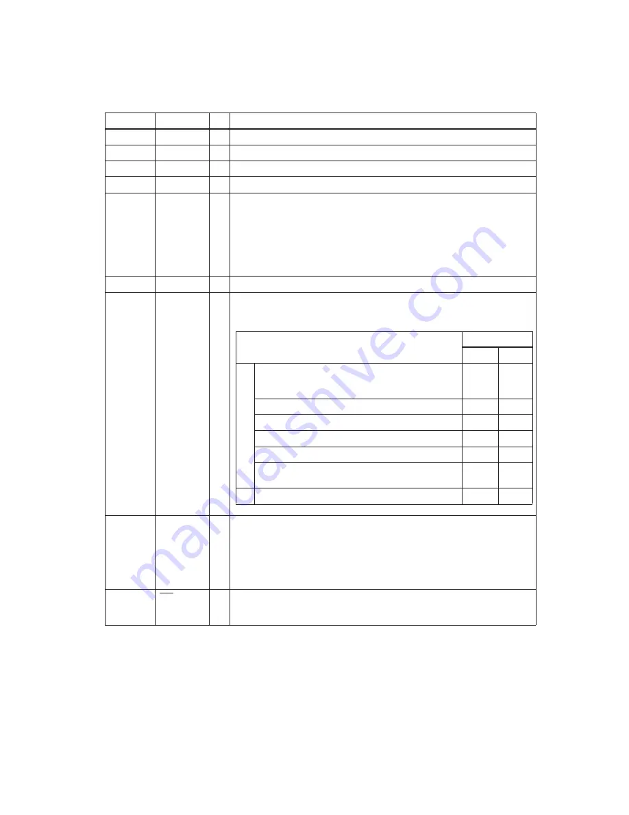
1) When DTR/DSR control is selected, this signal indicates whether the printer is
busy. SPACE indicates the printer is ready to receive data, and MARK indicates
the printer is busy. A busy condition can be changed using DIP SW 1-8 as follows:
2) When XON/XOFF control is selected:
This signal indicates whether the printer is correctly connected and ready to
receive data. SPACE indicates the printer is ready to receive data. The signal is
always SPACE except in the following cases:
❏
During the period after power on until the printer is ready to receive data.
❏
During self test.
25
INIT
I
Changing DIP switch setting enables this signal to be used as a reset signal for
the printer (see the DIP switch settings in the “Buttons and Switches” section of
this chapter). The printer is reset when the signal remains SPACE for 1 ms or more.
Printer
DIP SW 1-8 status
ON
OFF
1. During the period from when power is turned on
(including reset using the interface) to when the
printer is ready to receive data.
BUSY
BUSY
2. During self-test
BUSY
BUSY
3. During paper feeding using the paper FEED button
—
BUSY
4. When the printer stops printing for a paper-end. —
BUSY
5. When an error has occurred.
—
BUSY
6. When a temporary abnormality occurs in the
power supply voltage
—
BUSY
7. When the receive buffer becomes full. (See Notes.)
BUSY
BUSY
O
ff l
in
e
20
DTR
RS-232 interface connector pin assignments and functions
Interface Connector Pin Assignments
— 14 —
Summary of Contents for UP-250
Page 1: ...EXTERNAL PRINTER FEB 2000 MODEL UP 250 without price TECHNICAL MANUAL ...
Page 95: ... 86 END END Yes No Action 4 Replace main PCB Replace printer OK Action 4 mechanism assembly ...
Page 136: ... 127 ...
Page 149: ... 140 Main Circuit Board Parts Layout ...
Page 150: ... 141 RS 232 Serial Interface Circuit Board Parts Layout ...
Page 151: ... 142 IEEE 1284 Parallel Interface Circuit Board Parts Layout ...
Page 152: ...RS 485 Serial Interface Circuit Board Parts Layout 143 ...
Page 160: ... 151 Case Unit Lubrication Points Diagram 4 G 31 4 G 31 3 G 31 3 G 31 ...
Page 163: ... 154 EXPLODED DIAGRAM FOR TM U200B U210B NO 1 ...
Page 164: ... 155 EXPLODED DIAGRAM FOR TM U200B U200PB U210B U210PB NO 2 ...


