background image

V-R7000/V-R7100

– 46 –

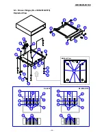
  1  V-R7000-BD

  2  V-R7100-BD

  3  V-R7000-U

  4  V-R7100-U

  5  V-R7000-C

  6  V-R7100-C

NOTE: 

When the Main PCB is replaced with a new one
•  Be sure to carry out ID registration (Test program → Device ID).
•  A OS software is installed in main board for spare parts. Please update appropriate OS software if necessary.

1

2

3

4

5

6

N

Item

Code No.

Parts Name

R

Remarks

Specification

Q'TY

N

3-10

10476872

BUTTON/POWER/BK

RJE504255-001V01

1

1

1

1

1

1

C

N

3-11

10476874

TAPE/BUTTON

RJE504292-001V01

1

1

1

1

1

1

C

N

3-12

10476873

CUSHION/BUTTON

RJE504291-001V01

1

1

1

1

1

1

C

N

3-13

10485322

PCB UNIT/LED

TK-RJE504271*001

1

1

1

1

1

1

C

N

3-14

10476877

CABLE/LED

RJE504276*001V01

1

1

1

1

1

1

C

N

3-15

10485323

PCB UNIT/MIC

TK-RJE504273*0011

1

1

1

1

1

1

C

N

3-16

10476878

CABLE/MIC

RJE504278*001V01

1

1

1

1

1

1

C

N

3-17

10476875

FG/PLATE/MIC

RJE504244-001V01

1

1

1

1

1

1

C

N

10485320

PCB UNIT/MAIN

TK-RJE504299*001

1

1

1

A

N

10485321

PCB UNIT/MAIN

TK-RJE504299*002

1

1

1

A

N

3-19

10494541

BACK- CHASSIS-ASSY

TK-RJE504298*001

1

1

1

1

1

1

X

N

3-20

10486985

LABEL/IF

RJE504340-001V02

1

1

1

1

1

1

C

N

3-21

10479677

BLIND/LCD

RJE504339-001V01

1

1

1

1

1

1

C

N

3-22

10322440

DALLAS

ASSY

TK-RJE502827*001

1

1

C

N

3-23

10409543

SPACER/DALLAS

RJE503900-001V01

1

1

C

N

3-24

10448859

FERRITE CORE

GTR-20-10-10

1

1

C

N

S2

SCREW

S-BDPT-3X8Z3

7

7

7

7

7

7

X

N

S3

SCREW

S-BDMA-3X4Z3

11

11

11

11

11

11

X

N

S4

SCREW

S-BDPT-2X4Z3

4

4

4

4

4

4

X

N

4-1

10476852

CHASSIS/BACK

RJE504237-001V01

1

1

1

1

1

1

X

N

4-2

SHEET/BATTERY

RJE504354-1

1

1

1

1

1

1

C

N

4-3

10485327

BATTERY ASSY

TK-RJE504303*001

1

1

1

1

1

1

C

N

4-4

10476853

BOX/BATTERY

RJE504247-001V01

1

1

1

1

1

1

C

N

4-5

10485326

PCB UNIT/TERMINAL

TK-RJE504331*001

1

1

1

1

1

1

C

N

4-6

10478536

SHEET/BLIND

RJE504313-001V01

2

2

2

2

2

2

C

N

S3

SCREW

S-BDMA-3X4Z3

1

1

1

1

1

1

X

N

S5

SCREW

S-BDMA-3X6Z3

1

1

1

1

1

1

X

3-18

4. BACK-CHASSIS-ASSY

Summary of Contents for V-R7000

Page 1: ...SERVICE MANUAL ELECTRONIC CASH REGISTER V R7000 V R7100 EX 870 JUL 2014 Ver 3 Mar 2017 ...

Page 2: ...ch commonly cause a small number of the pixels not to light or to remain lit all the time This is due to the characteristics of LCD panel yield in accuracy over 99 99 and permissible 802 11a n Restrictions Ɣ 7KLV SURGXFW LV IRU LQGRRU XVH RQO ZKHQ XVLQJ FKDQQHOV RU 0 Ɣ To ensure compliance with local regulations be sure to select the country in which the access point is installed Other Ɣ 3UHSDUH V...

Page 3: ... according to the instructions Batterie il y a danger d explosion si la batterie est remplacée par une batterie de type incorrect Mettez les batteries hors d usage au rebut en respectant les instructions LAN Connector Not used to a telecommunication network Port LAN Ne pas connecter à un réseau de télécommunication ...

Page 4: ...ing Method 6 3 HARDWARE TEST 8 3 1 List of Tests 8 3 2 Operation Check 9 3 3 Preparation Before Testing 11 3 4 Testing without Using the Test Application 12 3 5 Test Application 13 3 6 Other Testing 23 4 HARDWARE 24 4 1 Block Diagram 24 4 2 PCB Layout 25 5 DISASSEMBLY 27 5 1 Important 27 5 2 Flowchart 29 5 3 Procedure 30 6 EXPLODED VIEW PARTS LIST 43 6 1 Exploded View 44 6 2 Parts List 45 6 3 Draw...

Page 5: ...0 days Battery life 5 years used at 25 C Charge time Full charge in 3 hours used at 25 C Power supply power consumption 120 V AC 10 V 50 60 Hz 0 5 A 230 V AC 10 V 50 60 Hz 0 3 A 220 V to 240 V AC 10 V 50 60 Hz 0 3 A External interface Side of display SD SDHC memory card slot x 1 USB host port x 1 Earphone jack x 1 Rear of display COM port x 3 Drawer port x 2 DC jack x 1 USB host port x 3 SD SDHC m...

Page 6: ...Dallas key For operators to sign on and off 6 Rear cover Open when connecting the power supply or various devices 7 Speaker Output the audio 8 Main power switch cover Cover for the main power switch 9 Tilt knob Adjust the angle of the display 10 Earphone jack cover Cover for the earphone jack 11 Side cover Cover for various switches and slots at the left side 12 OFF switch Turn the power OFF 13 US...

Page 7: ...ce box VA B20EB EX IO UNIT 1A Drawer cable VA B30CB EX MDR CB 4 Display cable for customer QT 6061CB B EX DP CB 4C Length 40 cm Display cable for customer QT 6062CB B EX DP CB 4D Length 5 m DC Cable VA DC CORD1 EX IO CB 1 AC Adaptor AD S60240A EX ADP 1 1 4 Drawer List Type Model Specification EU UK US CANADA DI M DL 2814 D 26P1C B84RM 4 M DL 2815 D 26P1C B84SRM 4 M DL 2436 D 26P1C B55SRM 4 L DL 34...

Page 8: ... hold for 10 seconds or longer Shut down menu appears OFF switch Press briefly Shut down menu appears Press and hold for 10 seconds or longer Shut down sequence is executed Switch locations Main power switch Power switch OFF switch 1 6 Description of the Indicator Indicator Indicator Status Green light is ON Power is ON screen is ON Orange light is ON Power is ON screen is OFF Green and red lights...

Page 9: ... off display OFF Using the Power Switch 1 Press and hold the power switch for 10 seconds or longer 2 Touch the Power off display 2 Turn the main power switch OFF Remove the main power switch cover and turn OFF the main power switch Main power switch Main power switch cover NOTE The data may be damaged when above procedure is not done properly Do not use the main power switch to turn the main unit ...

Page 10: ...ating the OS from an SD card 1 Prepare an OS image file to be updated TIPS Definition of the OS image file name is as follows V R7000_OS version to be updated_from_OS version of the main unit ota NOTE Do not change the file name 2 Create a V R7000Update folder in the root directory of the SD card and copy the OS image file to the folder TIPS Multiple OS image files with different versions can be s...

Page 11: ... version to be updated_from_OS version of the main unit ota NOTE Do not change the file name About the file V R7000Update xml The file is used to identify the OS image file stored in the FTP or HTTP server Write the list of OS image files stored in the server as shown below NOTE Do not store the OS image file with the same OS version of the main unit in the file name Example Update V R7000_10028 f...

Page 12: ... USB 4 Port To be prepared USB Mouse 3 5 Test Application Installing the test application To be prepared USB Flash Drive for Test tool Test tool Touch Panel LCD Backlight mic speaker USB 1 Left Side To be prepared USB Flash Drive for testing SD 2 Left Side To be prepared SD Card for testing Head set To be prepared Head set Interface on the rear side HDMI To be prepared Monitor with the HDMI input ...

Page 13: ...e power is forcedly turned OFF Press the power switch to turn the power ON again Reset Switch Sleep State Operation Check 1 Press the power switch Check that the screen display disappears and the indicator changes from green to orange Press the power switch or touch the screen Check that the screen display appears and the indicator changes from orange to green TIPS If the backup battery is not cha...

Page 14: ...up battery icon 2 Tap Settings Display Power Down Pending and select 10 minutes Turn the main power switch OFF Main power switch 3 Check the followings The screen display remains the same Operation is possible The indicator changes from green to blue Turn the main power switch ON Check the followings The screen display remains the same Operation is possible The indicator changes from blue to green...

Page 15: ... directory This test tool is available in our Website servicecasio com USB Flash Drive for testing SD Card for testing Create a text file with the file name test and store it to the root directory 2 Connection diagram and names for testing USB Port 1 SD Slot 2 Earphone Jack COM 1 USB Port 2 micro USB Port LAN Port USB Port 3 USB Port 4 Drawer 5 V Drawer 24 V COM 2 COM 3 HDMI Port SD Slot 1 Indicator...

Page 16: ...access point with the LAN cable LAN Port 3 Tap Settings set Ethernet to ON Tap eth0 IP settings DHCP Apply Check that acquiring of an IP address starts and Connected appears 4 Return the network information to the settings recorded in Step 1 USB Port 3 USB Port 4 1 Connect a mouse to the USB Port 3 and then USB Port 4 USB Port 3 USB Port 4 Be sure that the pointer of the mouse appears on the scree...

Page 17: ...ources box 2 Connect the USB Flash Drive for Test tool to the USB Port 1 Tap Open Maneger USB Port 1 3 Tap USB Storage 1 FuncTestEX8700100010005 apk 4 Tap Next Install After completion of installation of the test application tap Open 5 If the settings for Wi Fi and Bluetooth are OFF a message appears accordingly Tap OK ...

Page 18: ... Untested Green Test result is OK Orange Test result is NG Setting Runs the Settings Exit Closes the test NOTE After completion of testing be sure to delete the test program by tapping Exit Yes 8 Remove the USB Flash Drive for Test tool TIPS Four applications are installed TIPS CFunction Test is the test application TIPS After closing the test program the four applications are deleted ...

Page 19: ...anel employed in this product uses high precision and substantial number of components which commonly cause a small number of the pixels not to light or to remain lit all the time This is due to the characteristics of LCD panel yield in accuracy over 99 99 and permissible After checking tap to show the judgment screen and then tap the obtained test result Backlight 1 Tap Backlight Move the slider ...

Page 20: ...he USB numbers used in the test program and the device differ with each other Name in the test program Name in the device USB 0 Left Side USB Storage 1 USB 1 Back USB Storage 2 In this manual the notation of the USB name is base on the name used in the device 2 Insert the USB Flash Drive to the USB Port 1 Tap USB 0 Left Side Automatic judgment is done and the test result appears USB Port 1 3 NOTE ...

Page 21: ... Head set Tap Head set Eaphone Jack 2 Record a voice and then play it back Check that the recorded voice is properly played back Starts recording Stops recording Plays back After checking the playback voice tap Discard to terminate the test As the judgment screen is displayed tap the obtained test result NOTE Perform the test without connecting the HDMI cable to the terminal ...

Page 22: ... is displayed on the monitor together with a sound After checking tap to show the judgment screen and then tap the obtained test result SD 1 Back NOTE Since the slot is located on the rear side carefully insert or remove the SD card 1 Insert the SD card to the SD Slot 1 Tap SD 1 Back Automatic judgment is done and the test result appears SD Slot 1 2 If the test result is NG check if the SD card is...

Page 23: ...e notation of the USB name is base on the name used in the device 2 Insert the USB flash drive to the USB Port 2 Tap USB 1 Back Automatic judgment is done and the test result appears USB Port 2 COM 1 COM 2 COM 3 NOTE Since the connector is located on the rear side carefully connect or disconnect the cable 1 Insert the loop back connector to COM1 Tap COM 1 COM 1 read Write Automatic judgment is don...

Page 24: ...the Drawer status close OK Green NG Red Tap to show the judgment screen and then tap the obtained test result Drawer 24 V NOTE Since the connector is located on the rear side carefully connect or disconnect the cable 1 Connect a drawer Tap Drawerb24V 2 Tap Drawer Open OK Drawer opens and the judgment result is indicated by the frame color of the Drawer status open OK Green NG Red 3 Close the drawe...

Page 25: ...udgment is done and the test result appears OK Green NG Red Tap to show the judgment screen and then tap the obtained test result Dallas Key TIPS Dallas Key model only 1 Tap Dallas Key Set the Dallas key Tap iButton ON Automatic judgment is done and the test result appears OK Green NG Red Tap to show the judgment screen and then tap the obtained test result ...

Page 26: ... the USB scanner 2 After entering the serial number tap Set Device ID Tap to show the judgment screen and then tap the obtained test result Reg UUID NOTE When the IOC PCB is replaced with a new one be sure to perform this item 1 Tap Reg UUID Tap UUID set Then the new UUID is written to the IOC PCB At the time when it is tapped the frame is painted in blue Tap to show the judgment screen and then t...

Page 27: ... with the Bluetooth device you have Wi Fi Test TIPS V R7100 only 1 Launch the Settings app Turn ON Wi Fi and set the access point and the connection settings 2 Launch the WLAN Tool app 3 Check the RSSI value and the network information Tips Guide for RSSI Value 20 to 50 dbm Excellent 60 dbm Better 70 dbm Good 80 dbm Not Good 90 to 100 dbm Bad dBm 45 ...

Page 28: ...MIC PCB E870 LED PCB E870 MCR PCB E870 MAIN PCB E870 IOC PCB Cable MCR IButton Mic Speaker Earphone jack USB host micro USB client LAN COM1 COM2 5V COM3 5V HDMI SD SDHC USB host USB host DC jack Drawer port 5V Drawer port 24V Reset switch SD SDHC USB host OFF switch BOOT switch LED Power switch Main power switch FFC FPC PCB ...

Page 29: ...V R7000 V R7100 25 4 2 PCB Layout E870 MAIN PCB ...

Page 30: ...V R7000 V R7100 26 E870 IOC PCB E870 COM PCB E870 LED PCB E870 MIC PCB E870 B CONTACT PCB E870 MCR PCB ...

Page 31: ...l tweezers Be sure to use plastic tweezers with flat tips Anti static tweezers are recommended There are several kinds of screws Be sure to use the correct type of screws when reassembling It is advisable to sort the screws as shown below after removing them When the Main PCB is replaced with a new one Be sure to carry out ID registration Test program Device ID A OS software is installed in main b...

Page 32: ...TAND ASSY itself is need to be replaced STAND ASSY Remove the main unit from the stand or VESA stand by reversing the installation order referring to V R7000 V R7100 Installation Manual When replacing the MCR refer to V R7000 V R7100 Installation Manual MCR The disassembly procedure explained here is based on the model V R7100 BD that is equipped with Dallas key Dallas key ...

Page 33: ... CASE ASSY PCB UNIT MAIN PCB UNIT IOC PCB UNIT MCR PCB UNIT COM LCD ASSY FRONT CASE ASSY PCB CHASSIS ASSY BACK CHASSIS ASSY Main components 77 5 66 Main components 0DLQ 3RZHU 6ZLWFK 63 5 Main components 7RXFK 3DQHO 3 3 81 7 0 3 3 81 7 0 ...

Page 34: ...ff two BLIND SCREW NOTE Carefully peel off so as not to give damage to the case A 3 Undo six screws NOTE Two kinds of screws are used S1 4 S2 2 COVER JACK COVER IF COVER MCR Screws S1 Screws S2 Screws S1 BLIND SCREW A 4 Remove the B CASE ASSY NOTE At this time the BUTTON OFF comes off BUTTON OFF ...

Page 35: ...ERY ASSY is damaged Plus terminal BATTERY ASSY A 5 The parts configuration of the B CASE ASSY is as follows COVER PW SW S2 CASE BACK COVER MCR BUTTON OFF LABEL SD FILM SW COVER IF TAPE DOUBLE BP COVER JACK COVER DP SW PANEL BACK B CASE ASSY Note on reassembling Set the BUTTON OFF to the case from the inner side and then assemble the B CASE ASSY BUTTON OFF ...

Page 36: ...y B 3 Peel off one tape that fixes the coaxial cable of the Wireless LAN antenna V R7100 only B 4 Undo six screws B 5 Remove the BACK CHASSIS ASSY NOTE The BACK CHASSIS ASSY is yet connected to the main PCB B 6 Peel off one tape and disconnect one connector Connector Tape Coaxial cables Screws S2 6 Tape Connector BACK CHASSIS ASSY ...

Page 37: ...V R7000 V R7100 33 Note on reassembling When fastening the screw use the hole with a mark Marking Run the antenna cable black and fix it with one tape Tape ...

Page 38: ...st item Backup Battery Operation Check 1 Peel off two tapes 2 Undo one screw 3 Remove the PCB UNIT TERMINAL Tapes Screw S5 PCB UNIT TERMINAL Hook 4 Undo one screw 5 Remove the BOX BATTERY and BATTERY ASSY BATTERY ASSY BOX BATTERY Screw S3 6 Replace the BATTERY ASSY and assemble the new one in the reverse order of disassembly ...

Page 39: ...C 2 Undo four screws C 3 Remove the PCB UNIT MAIN by sliding it sideways C 4 Disconnect one connector Connector Connectors Screw S3 Fix the ground wire together Screw S3 Screw S3 PCB UNIT MAIN Screw S3 Fix the ground wire and the earth plate together Note on reassembling Pay attention to the orientation of the ground wire If the orientation is improper the BACK CHASSIS ASSY cannot be assembled pro...

Page 40: ...D PCB UNIT IOC NOTE The PCB UNIT IOC cannot be removed if the PCB UNIT MAIN is not removed yet D 1 Disconnect two connectors Three connectors for the Dallas key model D 2 Disconnect one connector D 3 Peel off one tape release the connector lock and disconnect the FPC D 4 Undo four screws Screw S3 4 Connectors Connector Dallas key FFC Tape Unlock FPC PCB UNIT IOC TIPS Fuse information FU1 FU2 ...

Page 41: ...T COM F 1 Disconnect one FFC F 2 Undo two screws and remove the PLATE SUB F 3 Undo six lock screws and remove the PCB UNIT COM Screw S3 2 FFC PCB UNIT COM Lock screw 6 Note on reassembling Positioning places Be sure that no cables are pinched The PLATE SUB might be hard to assemble in the engaging portions of plates ...

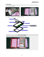
Page 42: ...G 2 Peel off one tape G 3 Remove two antennas silver parts V R7100 only G 4 Undo four screws NOTE Two kinds of screws are used S2 1 S3 3 G 5 Disconect one connector and remove a ferrite core Dallas key model only Tape Unlock FPC Screw S2 Screw S3 3 Tape Wireless LAN antenna 2 NOTE Carefully peel the antenna so as not to tear it Dallas key model Disconect one connector and remove a ferrite core ...

Page 43: ...silver part of the antenna stuck to the LCD 1 2 3 1 1 1 4 4 5 5 Check points Positioning places Three cables pass through the hole in the PCB CHASSIS ASSY Earth plate FG PLATE MIC Cable 2 Antenna cable 2 When the main power switch SW ASSY POWER is replaced with a new one pay attention to its orientation SW ASSY POWER ...

Page 44: ... tape SPEAKER Screw S6 2 Tape Cable CABLE MCR Fix with one tape Tape CABLE FFC IOC CABLE MCR FFC CABLE FFC IOC When replaced with a new one fold it as shown below 30 mm Reinforcing plate Reinforcing plate 50 mm 15 mm 45 mm E870 IOC E870 COM ...

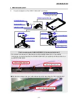
Page 45: ...SSY H 2 The parts configuration of the LCD ASSY is as follows PLATE LCD R CABLE LCD CABLE LCD BL PLATE LCD L CUSHION LCD V CUSHION LCD H CUSHION LCD V LCD ASSY S3 Note on reassembling Be sure that no dust or dirt is on the touch panel and LCD surfaces ...

Page 46: ...FRONT CASE ASSY Including Touch Panel Note on replacing the CASE ASSY FRONT of the wireless LAN model Two wireless LAN antennas are attached with the PCB UNIT MAIN and they are not available Carefully peel the two antennas from the FRONT CASE ASSY to be replaced and then stick them to a new FRONT CASE ASSY Antenna Black lead wire Antenna Gray lead wire NOTE Stick the antenna s silver part with adh...

Page 47: ...ithout prior notice 2 As for spare parts order and supply refer to the GUIDEBOOK for Spare Parts Supply published separately 3 The numbers in item column correspond to the same numbers in drawing 4 CASIO does not supply the spare parts without parts code 5 Refer to the latest Parts Price Code at PARTS FINDER on the Casio Service WEB site https www servicecasio com 6 Remarks Q ty Quantity used per ...

Page 48: ... 22 Dallas type 1 2 4 5 3 12 3 9 3 14 3 16 3 13 3 15 3 17 3 11 3 10 2 1 3 19 3 18 4 2 4 3 4 4 5 4 5 2 5 3 5 9 5 5 5 1 5 7 5 8 2 7 2 3 6 1 2 2 2 4 3 2 3 7 3 8 3 3 3 3 3 4 2 5 3 5 3 6 1 6 7 1 1 4 4 1 1 1 2 6 1 3 S2 S2 S7 S3 S6 S3 S3 S3 S3 S2 S3 S3 S3 S2 S4 S4 S5 S3 S2 B CASE ASSY BACK CHASSIS ASSY 3 1 4 6 5 6 3 20 3 21 1 5 STAND ASSY 6 S1 S8 ...

Page 49: ...1 1 1 1 1 C N 2 5 10476834 COVER PW SW BK RJE504258 001V01 1 1 1 1 C N 2 6 10481225 FILM SW RJE504336 001V02 1 1 1 1 1 1 C N 2 7 10487786 LABEL SD RJE504358 001V01 1 1 1 1 1 1 X N 2 8 10483812 COVER PW SW DALLAS RJE504252 001V02 1 1 C N S2 SCREW S BDPT 3X8Z3 1 1 1 1 1 1 X N 10488321 CASE ASSY FRONT TK RJE504295 009 1 1 1 1 C Including Touch Panel N 10488322 CASE ASSY FRONT TK RJE504295 010 1 1 C I...

Page 50: ... RJE504244 001V01 1 1 1 1 1 1 C N 10485320 PCB UNIT MAIN TK RJE504299 001 1 1 1 A N 10485321 PCB UNIT MAIN TK RJE504299 002 1 1 1 A N 3 19 10494541 BACK CHASSIS ASSY TK RJE504298 001 1 1 1 1 1 1 X N 3 20 10486985 LABEL IF RJE504340 001V02 1 1 1 1 1 1 C N 3 21 10479677 BLIND LCD RJE504339 001V01 1 1 1 1 1 1 C N 3 22 10322440 DALLAS䚷ASSY TK RJE502827 001 1 1 C N 3 23 10409543 SPACER DALLAS RJE503900...

Page 51: ...3DUWV 1DPH 5 5HPDUNV 6SHFLILFDWLRQ 4 7 1 66 6 3 5 9 1 3 7 68 5 9 1 3 81 7 2 7 5 1 3 81 7 20 7 5 1 63 5 3 3 3 1 2 9 1 6 66 32 5 7 5 1 3 81 7 0 5 7 5 1 0 5 7 5 1 6 6 5 6 0 1 6 6 5 6 0 67 1 66 7 5 6 833 5 67 1 5 9 1 DGDSWRU 7 5 1 3RZHU FRUG 7 5 RPELQHG RQO IRU 8 6 DQG DQDGD 1 29 5 66 7 5 68 66 5 5 5 9 HQJWK PP 6 6 5 6 20 6 6 5 6 3 60 1 9 7 5 RSPSOHWH XQLW RI 2 ER 1 9 0 5 7 5 RSPSOHWH XQLW RI 0 5 3 66...

Page 52: ...3 Drawer M type DL 2436 2814 2815 Exploded View DL 2814 2815 DL 2436 S6 S5 S5 S5 S5 S5 S6 S5 W1 W1 W1 W1 1 S1 S7 2 N1 N1 4 3 S3 S3 S4 S2 S2 Bottom View 6 5 9 7 8 5 11 10 10 10 12 5 15 16 16 17 17 18 19 19 18 14 13 14 13 15 ...

Page 53: ... 001V01 1 1 1 X 12 10413852 LOCK ASSY RJE500567 008V01 1 C 12 10413853 LOCK ASSY RJE500567 009V01 1 1 C 13 10230104 SUBASSY BILL HOLDER E341290 002V04 4 4 5 A 14 10276626 SPRING BILL HOLDER E441357 001V03 4 4 5 A 15 10194233 BRACKET BILL HOLDER E240845 001V02 1 1 1 X 16 10298565 CASE BILL E140505 002V03 1 1 1 X 17 10298555 SEPARATER BILL RJE500219 002V02 3 3 4 X 18 10298559 CASE COIN RJE500217 002...

Page 54: ...V R7000 V R7100 50 6 4 Drawer L type DL 3401 Exploded View 2 29 3 4 S1 5 S2 9 S4 12 11 10 1 30 18 13 21 26 28 27 25 6 20 S3 8 19 15 S4 17 16 14 11 24 23 S7 S7 32 7 S5 S1 17 22 S6 31 ...

Page 55: ...1 14 9487 0967 LINK ZD52864 1 C 15 5430 0208 E RING V042E00005 K1 1 C 16 9487 0968 UNLOCK UNIT ZD52860 1 C 17 1907 7930 SPRING UNLOCK ZD00254 2 C 18 1906 4150 RIVET 5X30 1 C 19 5580 1452 RING CS CSTW 5 1 C 20 9487 0969 ROLLER DELRIN DL 19B 2 B 21 9487 0970 COVER UNLOCK ZD52870 1 C 22 PANEL FRONT ZD53521 1 23 PLATE BOTTOM V094E00018 1 24 9487 0971 RUBBER PAD K3215H 4 C 25 9487 0972 CASE BILL V044E0...

Page 56: ...V R7000 V R7100 52 6 5 Drawer L type DL 3624 3625 Exploded View 14 15 S4 30 S3 S3 13 4 25 8 28 10 9 7 32 31 3 1 N1 26 5 6 S2 7 7 27 22 24 23 18 16 21 17 20 19 S5 S1 2 S6 S6 S6 11 12 S4 29 S7 S7 S7 S8 S8 ...

Page 57: ...0007K1 1 1 X 17 1907 7926 CASE COIN V023E00008K1 1 1 X 18 1041 4329 PLATE BILL PARTITION V094E00044K1 4 4 X 19 1041 4330 PLATE COIN PARTITION V094E00045K1 5 5 X 20 1907 7923 HOLDER PARTITION PLATE V067E00001K1 5 5 X 21 1902 6991 PLATE BILL HOLDER FIXINGZD00245 K2 1 1 X 22 9487 0385 STOPPER BILL HOLDER ZV27040 1 K2 5 5 X 23 6221 4902 HOLDER BILL V067E00002K1 5 5 A 24 6221 4904 SPRING BILL HOLDER ZD...

Page 58: ...er 1 Aug 2014 Correction of the EXPLODED VIEW P44 Correction of the PARTS LIST P45 to 47 Ver 2 Aug 2016 Correction of the EXPLODED VIEW P44 Correction of the PARTS LIST P47 Ver 3 Mar 2017 Correction of the HARDWARE TEST P11 Correction of the EXPLODED VIEW P44 Correction of the PARTS LIST P47 ...

Reviews: