- 3 -
N.B.
If this adjustment is not correct wedge insertion cannot take place
For safety reasons when no moulding is in place wedge insertion
cannot occur.
POSITIONING THE WEDGES (see Fig. 3)
Either turn off the air or switch off at the main switch.
Loosen the handles X and W.
Slide the cross bar (E) until the distributor head (H) is in the correct position
for the rear wedge.
Slide the locking handle forward (W) and lock into position.
Slide the cross bar to the forward position and slide the handle (X) to the
rear and tighten.
If wedges are being inserted at different levels check by raising the head with
the lever HA that no part of the moulding will prevent the distributor head
rising to the correct position.
In order to select the number of wedges press the keys 1 and 2.
Key 1 always corresponds
to
the position where the first wedge will be inserted.
This position is selected by the arrow keys
and
F
ig
3
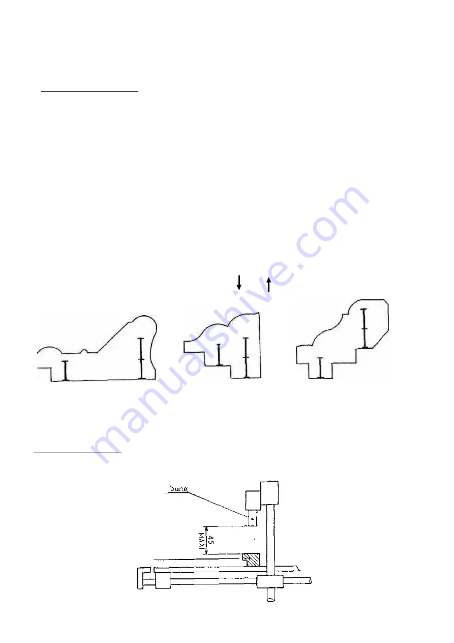
SETTING THE BUNG (0)
Check that the height between the top of the moulding and the bottom of the bung
is less than 45mm (1 3/4"). (see Fig. 4)
Fig 4
moulding


