USER & PARTS MANUAL
CS940
25
5.B
SAWING
5.B.a
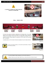
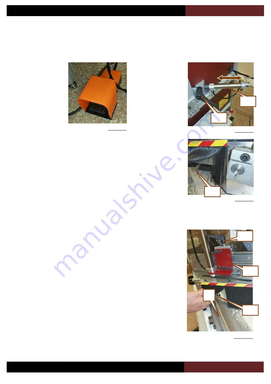
Setting the horizontal clamps
5.B.b
Setting the vertical clamps (optional)
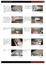
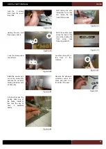
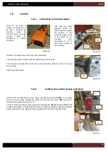
Unlock the handle
(
3)
, then move the clamp assy
(5)
so its extremity (
B1)
is in a stable
position on the moulding. Release the pedal and check that the rubber (
B1)
will hold the
moulding firmly without causing it to tilt.
The back of the moulding must be against the cutting guide
(6)
and the moulding must
be flat on the table. It is important to make sure the moulding is locked in a stable
position during the cut. Repeat same sequence for the other vertical clamp.
3
5
B1
Press on the pedal to
release the clamps and to
be able to introduce the
moulding
inside
the
machine. Keep the pedal
pressed
during
the
adjustment
of
clamp’s
sequence.
6
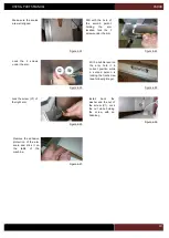
Figure 5-8
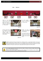
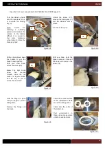
Proceed in the same way for the other horizontal clamp.
The moulding must be installed with the rebate facing to the blades.
The 2 horizontal clamps (PH) must be set so the extremities (EB) are at about 1 cm from
the moulding.
Keep the pedal pressed.
Still with the pedal
pressed,
unlock
the
(M2) handle and adjust
the
position
of
the
horizontal clamps (PH)
to the contact of the
moulding,
then
backwards of 1 cm to
allow easy loading of
the moulding.
PH
M2
Figure 5-5
Figure 5-6
Figure 5-7
EB
Summary of Contents for CS 940
Page 1: ...USER PARTS MANUAL Version 5 05 2017 Z27456 Version 1 07 2014 ...
Page 12: ...USER PARTS MANUAL CS940 12 2 E CUTTING CAPACITY ...
Page 13: ...USER PARTS MANUAL CS940 13 2 F NEEDED SPACE ...
Page 37: ...USER PARTS MANUAL CS940 37 ...
Page 46: ...USER PARTS MANUAL CS940 46 2 E CAPACITE DE COUPE ...
Page 47: ...USER PARTS MANUAL CS940 47 2 F PLAN D ENCOMBREMENT ...
Page 71: ...USER PARTS MANUAL CS940 103 V CERTIFICATE CERTIFICAT DE CONFORMITE ...
Page 72: ...USER PARTS MANUAL CS940 104 ...

