background image

Non contractual document - Cassese France

®

 - Document non contractuel

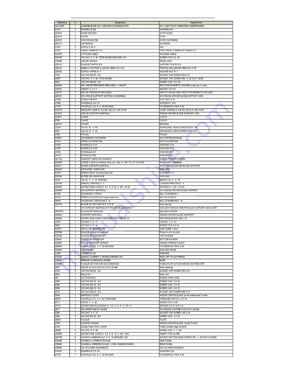
NOMENCLATURE / SPARE PARTS - CS1 CART

15

Z26150

Summary of Contents for CS1 CART

Page 1: ...PINNER Inventor and World No 1 Manufacturer of Picture Framing Machines Consumables Since 1976 CS1 CART USER PARTS MANUAL Version 2 11 2014 Cassese Communication Z26059 READ THIS MANUAL CAREFULLY BEFORE USING THE MACHINE ...

Page 2: ......

Page 3: ...LOADING WEDGES 3 WEDGE DISTRIBUTOR BLOCK 4 WEDGE POSITION STOP HANDLE inside of frame 5 WEDGE POSITION STOP HANDLE outside of frame 6 PEDAL 7 MAGNETIC ADJUSTABLE ROD CLAMP ASSEMBLY 8 CROSSBAR 9 STAPLING STOP 10 TABLE 11 WORK POSITION REFERENCE 9 6 5 10 2 1 8 3 4 11 7 Fig N 1 Fig N 2 AFTER UNPACKING THE MACHINE SET THE 4 FEET TO LEVEL THE MACHINE ...

Page 4: ... USE MEANS OF JOINING 6 LOADING CARTRIDGE WEDGES 6 CHANGING WEDGES SIZE 6 JOINING THE FRAME 7 MAINTENANCE A DISMANTLING THE WEDGE DISTRIBUTOR BLOCK 9 B CLEANING AND LUBRICATION OF THE WEDGE DISTRIBUTOR BLOCK 10 C REMOVAL OF THE WEDGE DRIVER BLADE 11 D INSTALLATION OF NEW WEDGE DRIVER BLADE 12 E UNJAMMING OF THE WEDGE DISTRIBUTOR BLOCK 13 F REMOVING THE SIDE PANEL 14 G REMOVING THE WORKING TABLE WI...

Page 5: ...Grease Tube TECHNICAL SPECIFICATIONS OF CS1 CART Minimum moulding width 5mm 1 4 Minimum moulding height 7 mm 11 16 Maximum moulding width mm Maximum moulding height 85 mm 3 11 32 Maximum stroke between first and last wedge at 45 140 mm 5 1 2 CASSESE Genuine Cartridge Wedges sizes 5 7 10 12 and 15 mm 3 wedge types Softwood Hardwood MDF Use only CASSESE Genuine cartridge wedges Machine gross weight ...

Page 6: ...he width and height of the moulding to join As a general rule a MINIMUM 2 mm clearance less than 1 8 above the wedges shall be respected Same size wedges can be stacked in order to avoid changing the size of wedge when joining tall mouldings AS A GENERAL RULE THE WEDGE POSITIONS MUST BE SELECTED VERTICALLY TO THE HIGHEST POINTS OF THE MOULDINGS SETTING AND STORING THE WEDGE POSITIONS Unlock the we...

Page 7: ...he wedge position stop handle 6 against the stapling stop 10 and tighten it Setting up the stapling position close to the inside of the frame Move backwards the sliding table E until you have reached the furthest position to the inside of the frame where you want to insert wedge s Then bring the wedge position stop handle 5 against the stapling stop 10 and tighten it Now the two positions of joini...

Page 8: ...p is ideal for flat mouldings or for hard to reach surfaces OPTIONS The round clamps are dedicated to complicated forms and sloped mould ings NEW MAGNETIC ADJUSTABLE CLAMPS Now with quick change magnetic clamps it is easy to change from chevron to a round clamp Accessories supplied with the machine Magnetic Chevron Clamp HARDWOOD SOFTWOOD ONE SIZE Z21525 Z18065 Z1783 Z1791 OPTIONAL Z24703 GOOD BAD...

Page 9: ... to change any parts on the machine or having to adjust anything For the best corner join reliability and performance use only CASSESE Genuine Cartridge Wedges WHITE REFERENCE 30303NCOI 30305NCOI 31305BDCO 30307NCOI 31307BDCO 30310NCOI 31310BDCO 30312NCOI 31312BDCO 30315NCOI 31315BDCO TYPE 3mm 5mm 5mm HW 7mm 7mm HW 10mm 10mm HW 12mm 12mm HW 15mm 15mm HW TYPE 3mm 5mm 5mm HW 7mm 7mm HW 10mm 10mm HW ...

Page 10: ... in place against each other hold the back fences 1 2 with your thumbs Move the sliding table E backwards until the wedge position stop handle 5 reaches the stapling stop 10 4th step Keeping the mouldings secure slowly push down the pedal 7 When the the magnetic adjustable rod clamp assembly 8 will press down on the mouldings speed up the movement so that the wedge is inserted more easily 5th step...

Page 11: ...is procedure First remove the cartridge of wedges from the underpinner CAUTION WHEN USING COMPRESSED AIR WEAR SAFETY GLASSES Unlock half a turn the locking screw of the wedge distribution block with the 2 5mm Allen key that is supplied with the machine Pull up the wedge distributor block Remove the wedge distributor block from the machine Pull up the crossbar in order to move the wedge distributor...

Page 12: ...es Insert the last piece as shown in the picture Before tightening the screws check the level of the pieces on the top of the wedge distributor block in order to have a perfect reassembly as shown in the picture Pull up the crossbar in order to insert the wedge distributor block on the wedge driver blade with the window facing the cartridge channel After having cleaned up the wedge distributor blo...

Page 13: ...der to help to slide the wedge driver blade up TO SLIDE THE WEDGE DRIVER BLADE UP WITH THE PEDAL 10 1 2 3 4 Push the pedal and maintain it Now the wedge driver blade is pulled up so you can remove it from its place 1st step 2nd step It is possible that you have to change the wedge driver blade Please follow the previous procedures A steps 1 to 5 and follow this procedure with the wedge distributor...

Page 14: ...ge channel and install the wedge distributor block Then lock it using the 2 5mm Allen key 1 2 D INSTALLATION OF A NEW WEDGE DRIVER BLADE Push the wedge driver blade fully in with a piece of wood or moulding press the pedal to engage the wedge driver blade entirely Check the wedge driver blade installation it should slide smooth with no resistance The upper end of the wedge driver blade stays out o...

Page 15: ...1 TO STEP 5 THEN PROCEED TO PROCEDURE C D COMPLETELY If the wedge driver blade or a wedge is jamming your wedge distributor block please follow this procedure Remove the cartridge located inside the underpinner and the magnetic adjustable rod clamp assembly If the cartridge doesn t come out loosen the screw of the wedge distributor block with a 2 5mm Allen key unlock the handle for loading wedges ...

Page 16: ...ogether to exit the mechanical parts from the frame Now you can access to the mechanical parts of the machine To access more easily to the mechanical parts you have to remove the side panel where is located the sticker Cassese France The following procedure is to be followed for removing or replacing the side panel of the machine Unscrew the 4 screws of the working table with the Allen Key 3mm Nex...

Page 17: ...he wedge distribution channel elastic cord you have to follow these differents steps which will be detailed Unscrew the nut with the socket spanner 7mm which maintain the elastic cord and the connection wire Now the elastic cord is just grasped by the last screw Push away the connection wire in order to free the working space Unscrew the last screw with the Allen key of 4mm Remove the elastic cord...

Page 18: ...Non contractual document Cassese France Document non contractuel ...

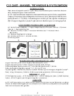
Page 19: ...1 2014 Cassese Communication Z26059 ASSEMBLEUSE MECANIQUE A PEDALE Inventeur et N 1 Mondial des Machines et Consommables pour l Encadrement d Art Depuis 1976 CS1 CART AVANT UTILISATION DE LA MACHINE LIRE IMPERATIVEMENT CE MANUEL D INSTRUCTIONS ...

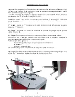
Page 20: ...OIR D AGRAFES 3 DISTRIBUTEUR AGRAFES 4 BUTEE POUR POSITION D AGRAFAGE intérieur du cadre 5 BUTEE POUR POSITION D AGRAFAGE extérieur du cadre 6 PEDALE 7 POTENCE DU PRESSEUR 8 CHEVRON PRESSEUR 9 BUTOIR 10 TABLE 11 REFERENCE POSITION TRAVAIL APRES AVOIR DEBALLE LA MACHINE REGLER LES 4 PIEDS PAR RAPPORT AU SOL 9 6 5 10 2 1 8 3 4 11 7 Fig N 1 Fig N 2 ...

Page 21: ...EMENT DES AGRAFES 6 CHANGEMENT DE TAILLE D AGRAFES 6 REMPLACEMENT DES AGRAFES 7 ASSEMBLAGE DU CADRE 7 MAINTENANCE A DEMONTAGE DU DISTRIBUTEUR D AGRAFES 8 B NETTOYAGE ET LUBRIFICATION DU DISTRIBUTEUR D AGRAFES 9 C RETRAIT DU MARTEAU 10 11 D INSTALLATION DU NOUVEAU MARTEAU 11 E DESENRAYEMENT DU DISTRIBUTEUR D AGRAFES 12 F RETIRER LE PANNEAU LATERAL 13 G RETIRER LA TABLE DE TRAVAIL AVEC LA PEDALE 13 ...

Page 22: ...D 1 clé Allen de 2 5mm 1 clé Allen de 3mm E Tube de graisse SPECIFICATIONS TECHNIQUES CS1 CART Largeur minimum profil 5mm Hauteur Minimum profil 5 mm Largeur maximum profil mm Hauteur maximum profil 85 mm Course d agrafage maximum entre la 1ère et la dernière agrafe à 45 140 mm Tailles de chargeurs d agrafes Cassese 5 7 10 12 et 15 mm 3 types d agrafes Bois Normal Bois Dur ou MDF N utiliser que le...

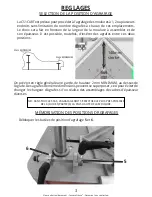
Page 23: ...e toutefois d insérer des agrafes entre ces deux positions On prévoit en règle générale une garde de hauteur 2 mm MINIMUM au dessus de l agrafe Des agrafes de même dimensions peuvent se superposer ceci pour éviter de changer le chargeur d agrafes si l on réalise des assemblages de cadres d épaisseur diverses NB DANS TOUS LES CAS L AGRAFAGE DOIT S EFFECTUER LE PLUS PRES POSSIBLE DE LA OU DES PARTIE...

Page 24: ...choisie Amener la butée 6 contre le butoir 10 et la bloquer Deuxième position d agrafage Côté intérieur du cadre Déplacer l équerre coulissante vers l arrière jusqu à la position choisie Amener la butée 5 en butée contre le butoir 10 et la bloquer Maintenant les deux positions d agrafages sont mémorisées et l équerre coulissante se déplace uniquement dans la limite de ces deux positions Wedges bet...

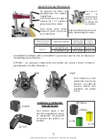
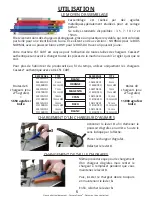
Page 25: ... détrompeur tourné vers le devant de la machine Il permet d éviter toute erreur dans l assemblage du cadre ACCESSOIRES FOURNIS AVEC LA MACHINE Le presseur chevron noir est idéal pour l assemblage de profils plats OPTIONS Les presseurs élastomères sont dédiés aux profils à fortes variations géométriques montée descente 5 Z21525 Z24703 BON MAUVAIS Faire attention à bien positionner le presseur chevr...

Page 26: ...t 15mm 6 3 Elles viennent dans des chargeurs écologiques grâce à un plastique recyclable qui sont colorisés par taille pour une identification facile Ils existent en deux versions NORMAL pour le BOIS NORMAL avec un poussoir blanc et HW pour le BOIS DUR avec un poussoir jaune Votre machine CS1 CART est conçue pour l utilisation de toutes tailles de chargeurs Cassese authentique sans avoir à changer...

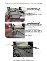
Page 27: ...lure sur la table le dos contre 2 et la pousser en appui jusqu à la 1ère moulure 3ème étape Maintenir 1 et 2 avec les moulures en position d agrafages 1 voir photos contre le butoir 10 4ème étape Toujours en maintenant les moulures enfoncez lentement la pédale Au moment où le presseur vertical entre en contact avec la moulure accélérez le mouvement de manière à faciliter l insertion de l agrafe Po...

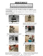
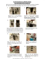
Page 28: ...E L AIR COMPRIME LE PORT DE LUNETTES DE PROTECTION EST OBLIGATOIRE Desserrer d un demi tour la vis du distributeur d agrafage avec la clé Allen de 2 5mm fournie avec la machine Tirer vers le haut la potence afin de sortir le distributeur d agrafage de son logement Faire coulisser vers le haut le distributeur d agrafage Retirer le distributeur d agrafage de la machine 1 2 3 4 5 Tirer vers le haut l...

Page 29: ...e pièce comme présenté sur la photo Avant de serrer les vis vérifier le nivellement des pièces en haut du bloc afin d avoir un remontage parfait comme sur la photo Tirer vers le haut la potence afin d insérer le distributeur d agrafes sur le marteau avec la fenêtre en direction du chargeur d agrafes Après avoir nettoyé le distributeur d agrafes assembler en premier ces 2 pièces Attention à ce qu e...

Page 30: ... vers le haut Il est possible que vous ayez à changer le marteau Veuillez suivre les procédures A et B précédentes et suivre cette procédure avec le distributeur d agrafes hors de la machine afin d éviter tout problème d agrafage Retirer le chargeur d agrafes de la machine avant toute manipulation FAIRE COULISSER LE MARTEAU VERS LE HAUT AVEC LA PEDALE 10 1 2 3 4 Après avoir retiré le chargeur d ag...

Page 31: ...sous le distributeur d agrafage et insérer un nouveau marteau dans le distributeur avec le trou du marteau indiqué dans le cercle vers le bas Replacer le distributeur d agrafes dans son logement avec la fenêtre vers le chargeur et installer le distributeur d agrafes puis le bloquer avec la clé Allen de 2 5mm L extrémité supérieure du marteau reste en dehors du distributeur d agrafage Remettre en p...

Page 32: ...us En utilisant la clé Allen 2 5mm desserrer la vis de blocage du distributeur d agrafes Puis soulever la potence avec les mains Le distributeur d agrafes va sortir de son logement Retirer le de la machine Si le distributeur d agrafes ne vient pas vous devez appuyer fortement sur la potence comme indiqué sur la photo Si l ancien marteau est bloqué dans le distributeur d agrafes REALISER LA PROCEDU...

Page 33: ...le haut Prenez la table de travail et la pédale ensemble pour sortir toutes les pièces mécaniques du bati Maintenant vous pouvez accéder aux parties mécaniques de la machine Ensuite déplacer sur le côté légèrement la table de travail Vue intérieure de la machine CS1 CART Prenez le panneau latéral et retirez le de son emplacement en le tirant vers le haut Pour accéder plus facilement aux pièces méc...

Page 34: ...a dernière vis Déplacer le fil de liaison afin de libérer l espace de travail Dévissez la dernière vis avec la clé Allen de 4 mm Retirer le tendeur de la vis Afin de remettre en place le système effectuez les étapes précédentes dans le sens inverse Pour remplacer plus facilement le tendeur du distributeur d agrafes vous devez suivre ces étapes différentes qui seront détaillés Tout d abord vous dev...

Page 35: ...Non contractual document Cassese France Document non contractuel NOMENCLATURE SPARE PARTS CS1 CART 15 Z26150 ...

Page 36: ...Non contractual document Cassese France Document non contractuel NOMENCLATURE CLASSIFICATION CS1 CART 16 ...

Page 37: ...Non contractual document Cassese France Document non contractuel 17 ...

Page 38: ...Non contractual document Cassese France Document non contractuel 18 ...

Page 39: ...Non contractual document Cassese France Document non contractuel 19 ...

Page 40: ...Non contractual document Cassese France Document non contractuel 20 ...

Page 41: ...Non contractual document Cassese France Document non contractuel 21 ...

Page 42: ... 6 180 CHANGE OF WORK POSITION CHANGEMENT DE LA POSITION DE TRAVAIL Take the 3mm Allen key for the table s screws Prendre la Clé Allen de 3mm pour les vis de la table This procedure is the same for UNI CART underpinners Cette procédure est la même pour les assembleuses UNI CART ...

Page 43: ...Non contractual document Cassese France Document non contractuel 23 AVANT BEFORE APRES AFTER 7 8 ...

Page 44: ...oid rubbing 7 Veillez à garder le même espace entre chaque côté de la table pour éviter les frottements 8 Put the table extension at the same level of the working table of your CS1 CART 8 Mettez la rallonge de table au même niveau de la table de travail de votre CS1 CART 6 With the help of the Allen key put each nut in front of the pathway of the screw 6 A l aide de la clé mettre chaque écrou deva...

Page 45: ...Non contractual document Cassese France Document non contractuel 25 OPTIONAL ACCESSORIES ON THE CS1 CART ACCESSOIRES OPTIONNELS SUR LA CS1 CART Z25147 Z25147 Z22027 Z22027 ...

Page 46: ...Non contractual document Cassese France Document non contractuel Z25450 Z25450 26 OPTIONAL ACCESSORIES ON THE CS1 CART ACCESSOIRES OPTIONNELS SUR LA CS1 CART ...

Page 47: ...Non contractual document Cassese France Document non contractuel ...
Page 48: ...e sa cassese com EXPORT DEPARTMENT Tel 33 0 1 64 42 49 71 Fax 33 0 1 55 02 16 60 33 0 1 64 42 49 73 33 0 1 55 02 29 48 Website www cassese com E mail export cassese com SERVICE APRES VENTE AFTER SALES DEPARTMENT KUNDENDIENST DIENST SERVICIO TECNICO Tel 33 0 1 64 06 24 51 Fax 33 0 1 55 02 16 64 tecsupport cassese com ...

Reviews: