background image

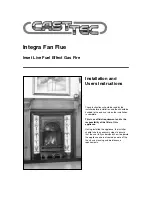
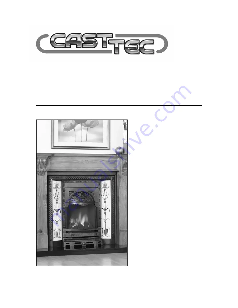
Integra Fan Flue

Inset Live Fuel Effect Gas Fire

Installation and
Users Instructions

These instructions should be read by the
installer before installation and then should be
handed to the end user when the installation
is complete.

This is an official requirement and is the
responsibility of the fitter of this
appliance.

Having installed the appliance, the installer
should take the necessary steps to ensure
that the user fully understands how to operate
the appliance and is also made aware of the
fire’s basic cleaning and maintenance
requirements.

Summary of Contents for Integra Fan Flue

Page 1: ...handed to the end user when the installation is complete This is an official requirement and is the responsibility of the fitter of this appliance Having installed the appliance the installer should t...

Page 2: ...10 Operating Sequence 11 Technical Data 11 Replacement Parts 11 Trouble Shooting GAS SAFE Engineer Only 12 Control Panel Wiring Diagram 13 Fault Finding Diagram 14 User Instructions 15 Cleaning and Ma...

Page 3: ...ng from cold This can be verified by traversing the canopy with a lighted smoke match see Spillage Test page 5 An isolation valve must be fitted adjacent to the appliance When closed this will allow t...

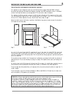
Page 4: ...the surround legs do not exceed a 150mm profile 6 If the 150mm profile is exceeded the width of the surround and the back panel should be increased by 25mm for each additional 12 5mm of profile depth...

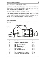
Page 5: ...e the flue pipe passes through the inner leaf a hole 100mm larger than the flue should be cut to allow a 50mm air gap around the entire flue circumference The vapour barrier on the back of the inner l...

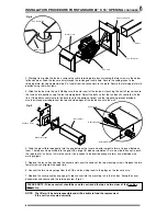
Page 6: ...ramic components in the separate carton 4 Remove the magnetic trim and store to one side to prevent any damage 5 Cut the foam sealing strip in plastic bag supplied to length and stick a continuous str...

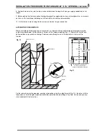
Page 7: ...that the fan box flanges are flat against the brickwork Mark the flue spigot so that it would be just below flush with the face of the fan box on final fix the spigot should not touch any part of the...

Page 8: ...the inner and outer spigot to form a ring seal between them The rope can be pushed into the gap with a large flat bladed screwdriver Care must be taken not to push the rope too far as it may fall int...

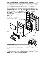
Page 9: ...g method may be employed using the cable fixing kit provided Drill four holes in the rear of the fireplace opening Fig 11 Securely fix the four eye bolts provided using suitable rawl plugs Feed one ca...

Page 10: ...h no gaps present 5 Locate the decorative frame on to the studs and secure with the two nuts provided 6 Insert the two screws into the lower holes in the decorative frame and carefully tighten ensurin...

Page 11: ...der Ref LEG18 c Fan Blower Order Ref LEG36 d Pressure Switch Order Ref LEG34 OPERATING SEQUENCE 11 REPLACEMENT PARTS TECHNICAL DATA This system is basically an add on to an existing manual fire The fa...

Page 12: ...oal set as per Ceramic Component Layout Instructions pages 17 18 5 The fire makes a roaring noise when lit Check That the front coal is seated correctly and the pilot hole is positioned correctly over...

Page 13: ...CONTROL PANEL WIRING DIAGRAM 13 b Blue lb Light Blue l Lilac o Orange y Yellow g Grey br Brown bk Black r Red w White g y Green Yellow p Purple Fig 15...

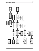
Page 14: ...FAULT FINDING DIAGRAM 14...

Page 15: ...set by turning the control knob from the pilot POSITION 2 through the maximum setting POSITION 3 to the minimum POSITION 4 The control knob is adjustable between these two positions 6 To turn off the...

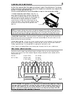
Page 16: ...the ceramic liners during cleaning as this is the only method that can be used to remove deposits The ceramic liners are very delicate and should be treated accordingly 3 Brass Trims and Frets The br...

Page 17: ...re that the lower part of the side cheeks sit on the front coal Fig 23 It is very important that all the coals are used and arranged as shown in order to achieve the desired flame picture It may be ne...

Page 18: ...the gaps are even It is important that the coals bridge the peaks of the fuel bed and are not placed in between This helps the flow of burnt gases and should give an even glowing fuel bed Fig 25 8 Pla...

Page 19: ...ill not light Remove the brass fret and check the pilot area for soot If soot is present remove all the loose coals and the front coal and thoroughly clean any debris in and around the pilot area If t...

Page 20: ...Unit 200 Glenfield Park Site 1 Philips Road Blackburn Lancashire BB1 5PF Tel 01254 695244 Fax 01254 695255 Web www legend fires com Email info legend fires com Issue B 17 6 11...

Reviews: