VENTILATION
No special ventilation bricks or vents are required in the room containing the appliance, providing that normal
adventitious room ventilation exists. The installer must determine this by carrying out a spillage test.
SPILLAGE TEST
To check for satisfactory clearance of products of combustion, close all doors and windows and leave the fire
burning for five minutes. Insert a lit smoke match on a vertical plane 50mm down, 50mm inside the canopy
opening. All the smoke must be drawn into the flue. If spillage occurs, allow a further ten minutes and repeat the
test. Should spillage still occur turn the appliance off and seek expert advice.
To continue the test: If an extractor fan is situated in the room the test should be repeated with the fan running. If
there is a connecting room with an extractor fan the test should be repeated with all the doors to that room open
and the extractor fan running.
INSTALLATION INTO TIMBER FRAMED DWELLINGS
Where removal of any part of the inner timber leaf of the wall is involved, the structural integrity of the wall must be
maintained and the advice of your local Building Control Department should be sought. If the property is under any
N.H.B.C. cover, it is advised that their advice on this modification should also be sought.
Standard methods of installation may be adapted for use in timber framed buildings, providing extra care is taken to
prevent combustible materials from contact with hot surfaces.
The appliance must be installed in accordance with British Gas documents DM2 and DM3 or the Institute of Gas
Engineers published procedure IGE/UP/7.
Special attention must be paid to the location of the studwork frame of the inner leaf and the appliance positioned
accordingly. Wires and pipes that run within the inner timber leaf must also be located and taken into account when
positioning the appliance.
INSTALLATION USING EXTENDED FIRE SURROUND OR FALSE CHIMNEY BREAST
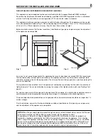
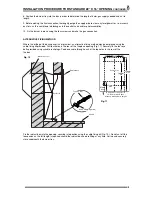
When using this method of installation the following amendments should be incorporated. 25mm clearance must be
allowed from the appliance firebox to any insulated combustibles. 75mm clearance must be allowed to any
unprotected combustibles.
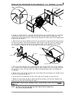
50mm minimum thickness of insulation should be provided around the flue pipe and gather hood. Where the flue
pipe passes through the inner leaf, a hole 100mm larger than the flue should be cut to allow a 50mm air gap
around the entire flue circumference. The vapour barrier on the back of the inner leaf should be cut and carefully
fixed to prevent any ingress of damp into the plasterboard layer. A layer of insulation will need to be provided to
insulate the surface of the inner wall from the heat effect of the flue. It may be advantageous to use a sheet of
Superlux board for this purpose. When setting the appliance into the inner wall find a suitable position between the
wall panel frames and carefully open up a hole to the dimensions given in the relevant section (section1), paying
careful attention to securing the damp proof membrane back into position. A Drip collar of galvanised or stainless
steel should be formed with the twisted joint on the underside of the flue to disperse drips. An air gap of 75mm
between all hot surfaces and the surrounding wall should be allowed, if protective insulation is used this may be
reduced to 25mm clearance.
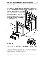
The exposed cavity should be sealed off using Superlux or a similar non-combustible board. The board should be
fixed at an angle, lower at the back so as to direct any moisture coming down to the outside wall. This board should
be fixed with screws, Unibond, or a similar adhesive. It is important to fit this board or a cavity tray to protect the
property and the appliance from drips of water. The sides of the opening where the cavity is exposed should be
packed with Rockwool or similar non-combustible material to a minimum depth of 50mm. The Rockwool packing
must extend from the base of the opening to the Superlux board.
NOTES ON ELECTRICAL INSTALLATION
1. External wiring must be correctly earthed, polarised and in accordance with relevant regulations/rules. In GB this
is the current I.E.E. Wiring Regulations. In IE reference should be made to the current edition of ETCI rules.
2. The method of connection to the electricity supply must facilitate complete electrical isolation of the appliance.
3. Connection may be via a fused double-pole isolator with a contact separation of at least 3mm in all poles.
The appliance must be positioned so that the switch is accessible.
4. If the appliance is to be fitted with a plug, the appliance must be positioned so that the plug is accessible.
5.
THE WIRES FEEDING THE FAN BOX MUST NOT BE ALLOWED TO TOUCH THE REAR OF THE FIRE BOX.
INSTALLATION REQUIREMENTS
CONTINUED
5
Summary of Contents for Integra Fan Flue
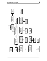
Page 14: ...FAULT FINDING DIAGRAM 14...

