Data logger operating manual
8
EN
8.4. Using the alarm hysteresis
If you use the alarm function without alarm hysteresis, then an alarm sounds
and is recorded each time the preset limit values are exceeded.
If your limit values have been selected very close to each other, then this means
that an alarm situation occurs very often.
For example, if you set a room temperature of 24 °C as the upper alarm limit
and a room temperature of 10 °C as the lower alarm limit and the room temper-
ature continually deviates between 23.5 and 25 °C during the measuring period,
then there will be many individual alarm signals created and recorded.
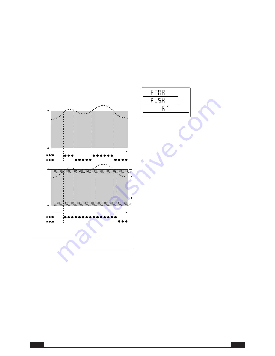
To prevent this, you can define an alarm hysteresis. With this setting, you define
a value by which the measured value must have returned to the valid value cor-
ridor, the good range, to switch off the alarm.
If an alarm hysteresis of 1 °C was set, the alarm in the previous example would
go off once as 24 °C was exceeded and then only stop as the temperature
drops below 23 °C again.
9. Notes on maintenance and operation
9.1. Battery change
If “LO bAtt” appears in the upper row of the display, then the batteries need
to be changed.
Data cannot be recorded while batteries are being changed. If data
recording is running, pause it and ensure that the data logger is in
operating mode M1 or M2 before changing the batteries.
To replace the batteries, open the battery compartment, remove the used batter-
ies and then insert new batteries, while observing the correct poles.
Time is maintained for at least a minute during battery change,
even when batteries are not inserted.
HYSTERESIS
Alarm display without hysteresis
Alarm display with hysteresis
Logging mode
Logging mode
Upper alarm
limit value
Valid value
corridor
“good range”
Lower alarm
limit value
flashing
static
Upper alarm
limit value
Valid value
corridor
“good range”
Lower alarm
limit value
flashing
static
Only use appropriate batteries which comply with the technical data. Other types
of batteries can cause operating errors. Do not use rechargeable batteries !
Do not dispose of used batteries in the household rubbish or throw them in the
fire; instead, dispose of them according to the relevant legal requirements.
9.2. Deleting measured data
The detected measured data are permanently saved in the internal Flash
memory. Even when resetting the device to factory settings or when there are
no batteries in the device, the measurement data remains in the memory and is
not deleted.
Saved data can only be deleted via the SmartGraph3 software as a whole and
not individually.
The deletion process takes approx. 2
minutes. During this time, the following
messages appears on the display:
“FOMA FLSH xxx %”.
During the entire deletion period, access
to the device is not possible and it does
not respond to requests from the Smart-
Graph3 software.
After memory has been completely
deleted, “FOMA FLSH 100 %” is shown
on the display. Afterwards, the display returns to normal operation.
Further detailed information about using the software is provided in the
software manual which you can open from the help function of the Smart-
Graph software.
9.3. Positioning for mobile use
For mobile measured value recording, the data logger can be positioned at any
site. Observe the permissible ambient conditions for operation (see technical
data). Due to its compact dimensions, the data logger can be hidden for non-in-
trusive applications.
9.4. Mounting on a wall
For stationary data detection, the data logger can also be mounted on a wall or
a similar holding device. A mount track is included in the scope of supply for fas-
tening.
For network operation, wall mounting is absolutely necessary.
Additional information about network operation is provided
in chapter 6.2.2.
9.5. Moving to another site
Especially when moving from cold to warm ambient conditions, e.g. when
moving into a heated room after storage in a car over night, depending on hu-
midity in the room, condensation may form on the printed circuit board.
This physical trait can lead to false measured values. Unfortunately, it is neces -
sary for the construction and cannot be prevented in any measuring devices.
In these cases, please wait approx. 5 minutes until the measuring device has
“acclimatised” before starting to measure.
Display for deleting measured data. In the
display, 6 % of the data have been
deleted so far.


