12 - 40
021774/07/14
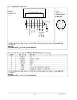
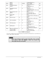
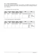
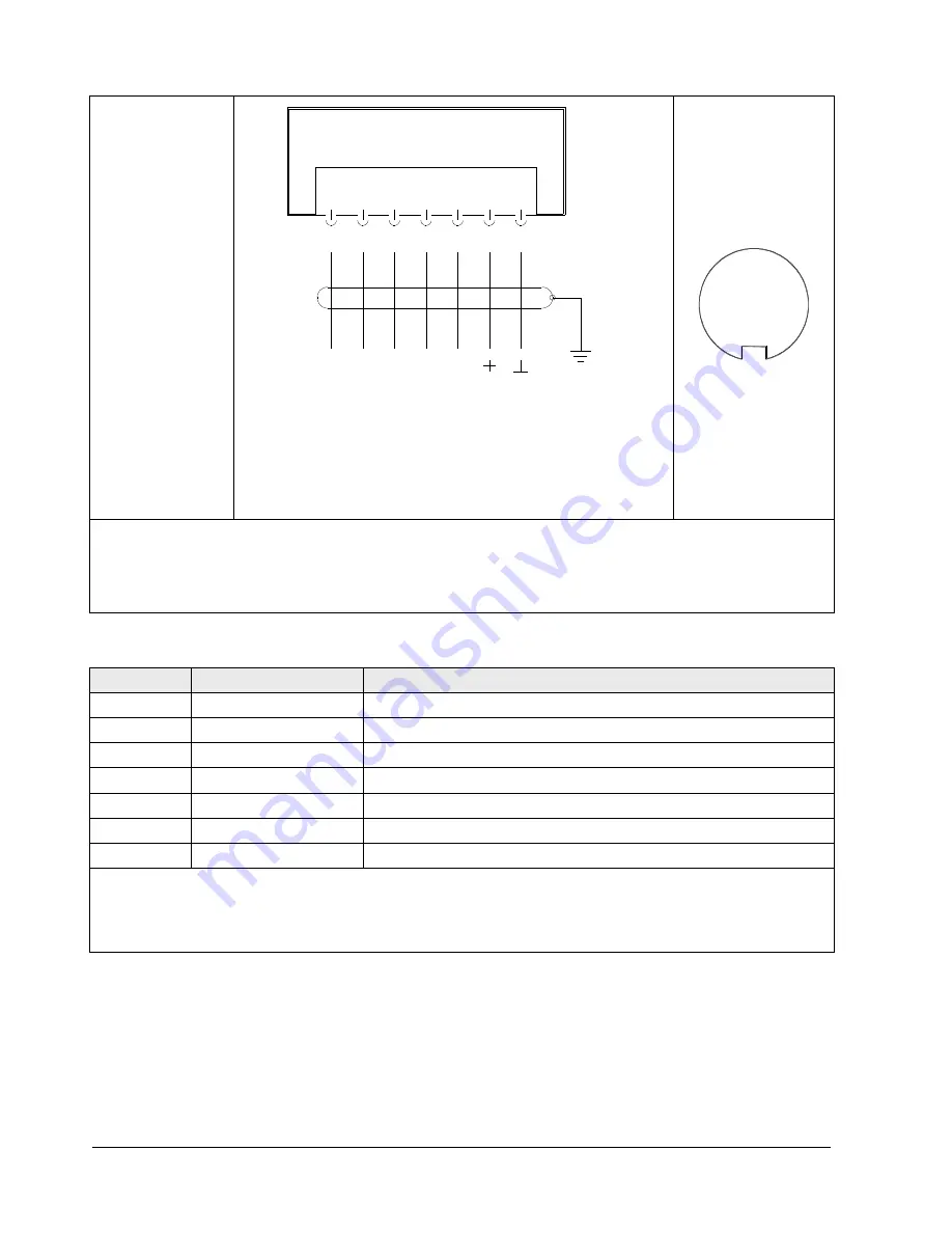
4.3.2 Diagram of connections
Order No.
4.9056.10.00x
View of
solder terminal
of mating connector
(cable socket)
2
4
6
3
5
1
7
*
With long transmission paths connection to the GND of data acquisition may reduce their susceptibility to
interference.
Important
:
* Do not connect DATA_GND to the supply voltage-GND.
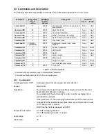
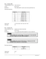
4.3.3 Connection using cable 509 584 / 509 585 (optional accessory)
PIN
Core colour
Function
1
WHITE
NC
2
BROWN
*
DATA _ GND
3
GREEN
DATA +
4
YELLOW
DATA -
5
GREY
NC
6
PINK
+ power 18...30V DC / 18...28V AC
7
BLUE
- power 18...30V DC / 18...28V AC
*
With long transmission paths connection to the GND of data acquisition may reduce their susceptibility to
interference.
Important
:
* Do not connect DATA_GND to the supply voltage-GND.
7 pol. Binder Steckverb. / Plug
7
Erde
Versorgung
DAT
A +
Earth
* DA
TA _
GN
D
Schirm / Shield
Power
18 ... 30 VDC
18 ... 28 VAC
DAT
A -
~ ~
NC
NC
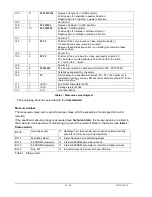
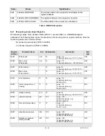
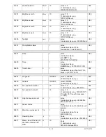
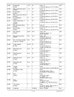
1 2 3 4 5 6

