background image

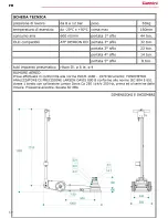
TECHNISCHES DATENBLATT

DE

28

Summary of Contents for YAK 510

Page 1: ...YAK 510 Ultima revisione 09 2010 ...

Page 2: ...GIO 5 MESSA IN SERVIZIO 5 UTILIZZO 6 GARANZIA 7 MANUTENZIONE RISERVATA ALL UTENTE FINALE 7 SPURGO DELL ARIA 7 MANUTENZIONE RISERVATA AD UN TECNICO PROFESSIONALMENTE QUALIFICATO 7 SCHEDA TECNICA 10 DISEGNI 47 RICHIESTA PARTI DI RICAMBIO 49 ESPLOSI 51 I 2 ...

Page 3: ...YAK 510 N I 3 ...

Page 4: ...amente proibito lavorare od operare in qualsiasi maniera sotto al mezzo che si sta sollevando fintanto che lo stesso non sia collocato sugli appositi cavalletti di sostegno DIS 2 Prima di procedere ad una operazione di sollevamento occorre bloccare l autoveicolo con il freno di stazionamento e o ponendo due cunei in corrispondenza delle ruote come illustrato in figura DIS 3 In fase di sollevamento...

Page 5: ...056 avendo l accortezza di mantenerli assemblati 4 Inserire il manubrio il distributore dell aria deve essere rivolto verso i pistoni con l innesto nell apposita scanalatura inserire i particolari precedentemente smontati nel foro del manubrio avvitare la vite n 1312 e successivamente serrare con il dado n 1296 5 Collegare i due tubi dell aria che escono dal manubrio negli appositi innesti rapidi ...

Page 6: ... costruttore del mezzo La ditta costruttrice declina ogni responsabilità per qualsiasi rottura del mezzo sollevato ed a danni a persone o cose dovute ad un utilizzo sbagliato del sollevatore stesso 2 La leva di posizionamento del manico A si trova a sinistra rispetto all operatore trasladola verso l alto si libera il sistema di arresto consentendo all operatore di scegliere una delle tre posizioni...

Page 7: ... trova sul fianco del serbatoio sotto il carter svitandolo si può controllare Nel caso si dovesse aggiungere dell olio nel serbatoio accertarsi che sia compatibile con l olio già presente per non compromettere l i ntegrità della macchina DIS 15 Se il livello dell olio è più alto del previsto anche di poco oppure se il cricco è stato capovolto succede facilmente durante il trasporto l olio viene es...

Page 8: ... piccolo colpo di martello Se non si riesce ad ottenere la tenuta della spilla sostituire la valvola KIT0265 completa di spilla n 83 Se dopo aver rimontato il sollevatore il carico scende ancora passare al punto seguente Svuotare completamente il serbatoio e il cilindro dall olio svitare il cilindro e controllare la guarnizione n 1131 se è rovinata sostituirla Rimontare il tutto serrando forte il ...

Page 9: ...he il rubinetto N 843 posto tra il serbatoio e la motopompa sia aperto In caso di anomalia nel funzionamento del cricco in salita o in discesa verificare la molla n 1046 la tenuta della sfera in gomma n 429 e la scorrevolezza del pistoncino n 130 I 9 ...

Page 10: ...I 10 ...

Page 11: ... 14 PUTTING INTO OPERATION 14 USE 15 WARRANTY 16 MAINTENANCE JOBS FOR THE END USER 16 AIR BLEEDING 16 MAINTENANCE RESERVED TO A PROFESSIONALLY QUALIFIED ENGINEER 16 TECHNICAL DATA SHEET 19 DRAWINGS 47 REQUESTING SPARE PARTS 49 EXPLODED DRAWINGS 51 EN 11 ...

Page 12: ...YAK 510 N EN 12 ...

Page 13: ...enance handbook The jack is an apparatus for lifting only and not for supporting it is therefore absoltely forbidden to work in any way under the vehicle being lifted until it is placed on the relative stands DWG 2 Before starting to lift a vehicle it has to be blocked with the parking brake and or by putting wedges under the wheels as illustrated in the figure DWG 3 If the vehicle is loaded check...

Page 14: ...air distributor must be facing the pistons inserting the coupling in the groove put the parts removed previously into the hole of the handle tighten screw 1289 and then tighten nut 1296 5 Connect the two air pipes between the jack and the handle with the quick couplings on the chassis respecting the colour indication as showed on the sticker on the chassis itself DWG 11 CONNECTION TO THE COMPRESSE...

Page 15: ...stopping system is released so the worker can then choose one of the three possible handle positions DWG 13 3 When control B is in the perfectly central position the jack is in the idle status 4 By turning control B located near the handle towards the right in relation to the worker the jack lifts the load 5 By turning control B located near the handle towards the left in relation to the worker th...

Page 16: ...sport the oil is expelled through the suction pump as mist This phenomenon disappears on Its own when the oil level hase been restored If the oil inside the tank exceeds the level by a lot it is advisable to remove some until it is back in the norm AIR BLEEDING Each time the jack is serviced removing and refitting parts connected to the tank and motorpump it is advisable to bleed off all air Bleed...

Page 17: ... its seat with a light blow with a hammer If it is not possible to obtain a seal on the pin replace the valve KIT0265 complete with the pin 83 If the load still falls even after fitting the jack carry out the following step Completely drain the tank and the cylinder of oil loosen the cylinder and check the washer 1026 if it is damaged replace it Refit everything and tighten the cylinder Fill the o...

Page 18: ...ift up very slowly check that the tap 843 between the tank and motor pump is open If the jack is malfunctioning when lifting or lowering check the spring 1046 the rubber ball seal 429 and the smooth sliding of the piston 130 EN 18 ...

Page 19: ...EN 19 ...

Page 20: ...GEN 22 VERPACKUNG 23 INBETRIEBNAHME 23 BENUTZUNG 24 GARANTIE 25 DEM BENUTZER VORBEHALTENE WARTUNG 25 ENTLÜFTUNG 25 WARTUNG DURCH EINEN GESCHULTEN WARTUNGSTECHNIKER 26 TECHNISCHES DATENBLATT 28 ZEICHNUNGEN 47 ERSATZTEILBESTELLUNG 49 EXPLOSIONSZEICHNUNGEN 51 DE 20 ...

Page 21: ...YAK 510 N DE 21 ...

Page 22: ...liegenden Bedienungs und Wartungshandbuchs kennt Der Heber ist ausschließlich ein Gerät zum Anheben und nicht zum Stützen es ist daher absolut verboten auf irgendeine Weise unter dem Fahrzeug das man anhebt zu arbeiten oder tätig zu sein solange es sich nicht auf den entsprechenden Stützböcken befindet ABB 2 Vor einem Hebevorgang muss das Fahrzeug mit der Standbremse blockiert werden und oder mit ...

Page 23: ...erungen aus dem Karton nehmen 2 Die beiden Muttern Nr 1296 aus dem Inneren des Chassis lösen ABB 10 3 Die Schraube Nr 1312 aus dem Chassis lösen und die Teile Nr 2032 und 2056 entfernen und sie dabei zusammengebaut lassen 4 Die Stange mittels der Kupplung in die entsprechende Nut einsetzen der Luftverteiler muss auf die Kolben hin gerichtet sein die vorher abmontierten Teile in das Loch der Stange...

Page 24: ...m Installationsort geltenden Umweltschutzvorschriften erfolgen Die Verschrottung vom Heber und seiner Bauteile muss unter Beachtung der am Installationsort geltenden Bestimmungen erfolgen BENUTZUNG Die in dieser Handbuch beschriebenen Sicherheitsbestimmungen unbedingt einhalten 1 Den Heber an der Hebestelle ansetzen die vom Fahrzeughersteller im Handbuch angegeben ist der Hersteller vom Heber über...

Page 25: ...egenden Handbuch beigelegte Kärtchen DEM BENUTZER VORBEHALTENE WARTUNG Für eine lange Lebensdauer des Hebers wird empfohlen die Kolben alle fünfzehn Tage von außen zu reinigen Mindestens 2 Mal pro Jahr den Ölpegel im Tank kontrollieren Diese Kontrolle muss mit ganz abgesenkten Kolben erfolgen Der Ölpegel muss auf der Höhe der Mutterschraube sein die sich auf der Seite des Tanks unter der Verkleidu...

Page 26: ...das Innere sorgfältig ausblasen dann alles wieder montieren die Kugeln 40 und 521 gegebenenfalls wieder einschlagen Erneut entlüften wie auf der vorausgehenden Seite beschrieben dann den Heber wieder in die normale Position bringen und den Hahn wieder öffnen Der Hydraulikblock 1152 kontrollieren und dabei besonders darauf achten dass die Kolben 89 und 264 die die Ventile zum Absenken öffnen und sc...

Page 27: ... muss Ölverlust an der Saugpumpe 0935 Kontrollieren ob zuviel Öl im Tank ist Falls der Heber umgekippt worden ist legt sich der Ölverlust nach kurzer Zeit Sollte der Schalldämpfer 267 Öl verlieren und der Punkt B nicht nötig gewesen sein muss die Unversehrtheit des Hydraulikblocks überprüft werden 1152 Die Dichtungen 90 und 26 ersetzen oder den gesamten Hydraulikblock ersetzen 1152 ANDERE FÄLLE Fa...

Page 28: ...DE 28 ...

Page 29: ...32 MISE EN SERVICE 32 UTILISATION 33 GARANTIE 34 MAINTENANCE RE SERVE E A L UTILISATEUR FINAL 34 PURGE D AIR 34 ENTRETIEN RESERVE A UN TECHNICIEN PROFESSIONNELLEMENT QUALIFIE 35 FICHE TECHNIQUE 37 DESSINS 47 DOMANDE PIECES DE RECHANGE 49 VUES E CLATE ES 51 FR 29 ...

Page 30: ...YAK 510 N FR 30 ...

Page 31: ... support il est donc rigoureusement interdit de travailler et d intervenir de quelque manie re qui soit sous le ve hicule en cours de levage tant que celui ci n est pas positionne sur les be quilles de soutien FIG 2 Avant de proce der a une ope ration de levage bloquez le ve hicule en actionnant le frein de stationnement et ou en positionnant deux coins de blocage au niveau des roues comme dans l ...

Page 32: ...083 et 0304 en veillant a maintenir le tout ensemble 4 Introduisez la barre le distributeur d air doit e tre tourne vers les pistons avec l enclenchement dans la rainure pre vue a cet effet introduisez les e le ments pre ce demment de monte s dans le trou de la barre vissez la vis n 1289 puis serrez avec l e crou n 1296 5 Raccordez les deux tuyaux de l air qui sortent de la barre de commande dans ...

Page 33: ...eusement les normes de se curite de crites dans ce manuel 1 Placez le cric sous la be quille de soutien comme le montrent les indications sur le manuel du fabricant du ve hicule le fabricant du cric ne sera pas tenu pour responsable des e ventuelles ruptures du ve hicule souleve ni des blessures cause es aux personnes ni me me des de ga ts mate riels occasionne s dus a une utilisation errone e du ...

Page 34: ...ment abaisse s Le niveau d huile doit e tre a la hauteur du petit boulon qui se trouve sur le co te du cylindre re servoir en le de vissant il est possible de le contro ler S il s ave re ne cessaire d ajouter de l huile dans le re servoir s assurer qu elle est compatible avec l huile qui s y trouve de ja afin de ne pas compromettre le bon fonctionnement de la machine FIG 15 Si le niveau d huile es...

Page 35: ... 521 re pe tez l ope ration de vidange illustre e a la page pre ce dente puis remettez le cric en position normale et rouvrez le robinet Contro lez le petit bloc hydraulique 1052 en faisant particulie rement attention a ce que les petits pistons 89 et 264 qui commandent l ouverture et la fermeture des soupapes de descente ne soient pas devenus rigides si tel est le cas de montez les et graissez le...

Page 36: ...ge Perte d huile du dispositif de de pression 935 contro lez la quantite excessive d huile dans le reservoir Si le cric a e te renverse la perte s arre tera rapidement Si la fuite d huile concerne le silencieux 267 et que l application du point B n a pas e te ne cessaire ve rifiez l inte grite du petit bloc hydraulique 1052 remplacez les joints 90 et 26 Ou bien remplacez tout le bloc hydraulique 1...

Page 37: ...FR 37 ...

Page 38: ... EN SERVICIO 41 EMPLEO 42 GARANTI A 43 MANTENIMIENTO RESERVADO AL USUARIO FINAL 43 PURGADO DE AIRE 43 MANTENIMIENTO RESERVADO A UN TE CNICO PROFESIONALMENTE CUALIFICADO 43 FICHA TE CNICA 46 DIBUJOS 47 SOLICITUD DE PIEZAS DE REPUESTO 49 DIBUJOS DE DESPIECE 51 Es 38 ...

Page 39: ...YAK 510 N Es 39 ...

Page 40: ...soporte por lo tanto queda absolutamente prohibido trabajar u operar de cualquier modo debajo del medio que se esta levantando hasta que el mismo se coloque sobre los relativos caballetes de soporte DIB 2 Antes de realizar una operacio n de elevacio n es necesario bloquear el vehi culo con el freno de aparcamiento y o colocando dos tacos cerca de las ruedas como se ilustra en la figura DIB 3 Duran...

Page 41: ...tencio n a mantenerlas ensambladas 4 Introducir el manubrio el distribuidor del aire debe estar dirigido hacia los pistones con la muesca en la ranura relativa introducir las piezas antes desmontadas en el orificio del manubrio enroscar el tornillo n 1289 y posteriormente ajustar con la tuerca n 1296 5 Conectar los dos tubos del aire entre el gato y el manubrio en los empalmes ra pidos en el chasi...

Page 42: ...o declina cualquier responsabilidad por rotura del medio levantado asi como por dan os a personas o cosas debidos a un uso erro neo del gato 2 La palanca de posicionamiento del manubrio A se encuentra a la izquierda con respecto al operador traslada ndola hacia arriba se libera el sistema de parada permitiendo al operador elegir una de las tres posiciones del manubrio DIB 13 3 Cuando el mando B es...

Page 43: ...la ma quina DIB 15 Si el nivel de aceite es ma s elevado del previsto incluso si es so lo un poco o bien si el gato ha sido dado vuelta suele suceder a menudo durante el transporte el aceite es expulsado a trave s del depresor en forma de niebla Este feno meno desaparece so lo cuando el nivel de aceite se restablece Si el aceite dentro del depo sito supera mucho el nivel indicado se aconseja extra...

Page 44: ... cierre de las va lvulas de bajada no se hayan vuelto poco corredizos en tal caso desmontarlos y engrasarlos EL GATO SUBE PERO BAJO CARGA SE BAJA Desmontar el grupo 1052 y comprobar que debajo de las va lvulas 40 y 83 no hayan impurezas despue s de haber lavado cuidadosamente readaptar el alfiler 83 en su sede dando un pequen o golpe de martillo Si no se consigue obtener el sellado del alfiler hay...

Page 45: ...a pe rdida se detendra pasado un breve lapso de tiempo Si la pe rdida de aceite se presenta en el silenciador 267 y el punto B no ha sido necesario debera comprobarse el estado del bloque hidra ulico 1052 Cambiar las juntas 90 y 26 O bien cambiar todo el bloque hidra ulico 1052 OTROS CASOS Si los pistones salen con mucha lentitud comprobar que el grifo 843 colocado entre el depo sito y la motobomb...

Page 46: ...Es 46 ...

Page 47: ...Es 47 ...

Page 48: ...Es 48 ...

Page 49: ... MENGE REQUESTING SPARE PARTS WHEN ORDERING SPARE PARTS THE FOLLOWING MUST BE SPECIFIED 1 LIFT MODEL 2 SERIAL NUMBER 3 PART NUMBER 4 PART DESCRIPTION 5 QUANTITY DESIRED DOMANDE PIECES DE RECHANGE LA DEMANDE DE PIECES DE RECHARGE DOIT ETRE DES PRE CISIONS SUIVANTES 1 MODEL DE L APPAREIL DE LEVAGE 2 NUME RO DE SE RIE DE L APPAREIL DE LEVAGE 3 NUME RO DE TRAVAIL 4 DENOMINATION DU DE TAIL 5 QUANTITE S...

Page 50: ...Es 50 ...

Page 51: ...Es 51 ...

Page 52: ...Es 52 ...

Page 53: ...Es 53 ...

Page 54: ...Es 54 ...

Page 55: ...Es 55 ...

Page 56: ...Es 56 ...

Page 57: ...Es 57 ...

Page 58: ...Es 58 ...

Page 59: ......

Page 60: ......

Reviews: