background image


Section 4, Page 2


01/2001, CATTRON


- THEIMEG

TM


Maintenance Procedures. 

Preventive Maintenance

 is a periodic check of the system to keep it functioning at peak 

performance. Preventive maintenance can also help prevent breakdowns and equipment outages 
by identifying potential problems before they become real problems.  

Corrective Maintenance

 refers to fixing a problem once it has occurred. The goal of corrective 

maintenance is to get the system back on line as quickly as possible with a minimum impact on 
operations. 

Preventive maintenance – PS Controllers. 

Preventive maintenance for PS controllers is minimal because they are extremely durable and reliable 
units.  Preventive maintenance procedures are detailed in the following sub paragraphs: 

Daily Visual Inspection. 

Before use, visually inspect the controller for cleanliness, physical damage, and security of 
external parts (screws, switches, rubber grips, etc.). CATTRON-THEIMEG

 emphasizes 

that regular visual inspections not only mean quickly locating a source of potential problems, 
but also may prevent serious problems from developing later. 

Annual Netting Check. 

Netting means that the receiver and transmitter of the radio control system are aligned on the 
same frequency. It is very important that the receiver is exactly tuned to the frequency 
required. This check should be done 

once a year by a qualified radio technician utilizing 

calibrated test equipment.


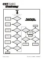
Troubleshooting – PS Controllers. 

A basic Troubleshooting Guide is provided on page 4 of this section.  When troubleshooting the 
controller, the other major components of the remote control system (power supply and 
receiver/decoder) should be fully operational.  The operator should also be located within 500 feet (160+ 
meters) of the target receiver/decoder.  

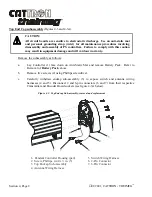
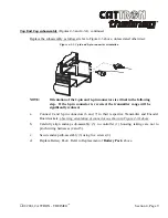
Corrective maintenance – PS Controllers. 

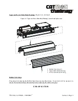
Corrective maintenance for PS Controllers is restricted to replacing the Battery Pack, Rubber Side Grips, 
Top End Cap sub-assembly, Bottom End Cap sub-assembly and Upper Main Body Housing.  Refer to 
the 

Disassembly/Assembly

 procedures below when removing and replacing items.  On completion of 

any assembly procedure and before placing the PS Controller into operational service, carry out a 
Functional Check as follows:  

Summary of Contents for i-Key

Page 1: ...PENDANT STATION CONTROLLER OPERATION MAINTENANCE MANUAL CUSTOMER MODEL NUMBER SERIAL NUMBER FREQUENCY ASSIGNMENT ADDRESS ASSIGNMENT MANUAL P N 68C PS REV 000 01 2001 ...

Page 2: ......

Page 3: ...ontroller to CATTRON THEIMEG for repair we recommend the coded i Key last used with the unit be returned with the unit Before returning a PSEZ or PSCS Pendant controller to CATTRON THEIMEG for repair we strongly recommend you record the operating address and frequency assigned to the controller as you will be required to re program these operating parameters after we return your controller Refer t...

Page 4: ... Semiconductor OPR Operate CS Crane Specific PRC Portable Remote Control DC Direct Current PS Pendant Station DOC Department of Communication Canada PTO Push to Operate DP Dual Pressure RF Radio Frequency EDP Electronic Data Processing RFI Radio Frequency Interference EEPROM Electrically Erasable Programmable Read Only Memory RST Reset Relay EMI Electro Magnetic Interference SP Single Pressure EPR...

Page 5: ...chnology AT family of controllers that have been customized and pre programmed to your exact specification you should skip Section 5 in its entirety as the frequency and address programming procedures contained therein do not apply to your controller If you are using our PSEZ or PSCS family of controllers you should include Section 5 as you will be required to verify program the system address and...

Page 6: ... MAINLINE SO THAT STOP COMMANDS OR FAULT CONDITIONS MONITORED BY AUTOMATIC SAFETY OVERRIDE ASO CIRCUITRY WILL DE ENERGIZE THE MAINLINE CONTACTOR AND SET THE EQUIPMENT BRAKE FAILURE TO COMPLY WITH THE ABOVE WARNINGS MAY RESULT IN SERIOUS INJURY OR DEATH TO PERSONNEL AND DAMAGE TO EQUIPMENT WARNINGS MORE THAN ONE REMOTE CONTROL SYSTEM MAY BE USED AT AROUND OR NEARBY YOUR OPERATING FACILITY THEREFORE...

Page 7: ...RGIZES TO PREVENT A POTENTIALLY HAZARDOUS SITUATION YOU SHOULD IMMEDIATELY PRESS THE RED STOP BUTTON ON YOUR REMOTE CONTROLLER AFTER COMPLETION OF CRANE OPERATIONS SUCH ACTION WILL INSURE THE PARKING BRAKE IF EQUIPPED AND CONFIGURED AS ABOVE IS SET PREVENTING UNINTENTIONAL MOVEMENT OF THE CRANE OR TRACKED MACHINE FAILURE TO COMPLY WITH THIS WARNING MAY RESULT IN SERIOUS INJURY OR DEATH TO PERSONNE...

Page 8: ...gnet circuits vacuum circuits grab pump motors fire suppression etc CONTACT CATTRON THEIMEG FACTORY FOR INFORMATION REGARDING PROPER INTERFACE TO SAFETY CRITICAL BI STABLE MAINTAINED FUNCTIONS SHOULD CATTRON THEIMEG PSCS AND PSEZ PORTABLE REMOTE CONTROL SYSTEMS BE INADVERTENTLY CONFIGURED TO INTERFACE DIRECTLY WITH SAFETY CRITICAL BI STABLE MAINTAINED FUNCTIONS AT YOUR OPERATING FACILITY DAMAGE TO...

Page 9: ...Zinc Lithium or Ni Cad Batteries are not to be used with this adapter Damage to batteries will occur if this adapter is used for battery charging CAUTION All circuit boards are sensitive to electrostatic discharge Use an anti static mat and personal grounding strap wrist for all maintenance procedures involving disassembly and assembly of PS Controllers Failure to comply with this caution may resu...

Page 10: ...ower discharge and ground a circuit before touching it Adhere to all lock out tag requirements DO NOT SERVICE OR ADJUST ALONE Do not attempt internal service or adjustment of equipment unless another person capable of rendering aid and resuscitation is present FINGER RINGS JEWELRY Finger rings have caused many serious injuries Remove rings watches and other metallic objects that may cause shock or...

Page 11: ...ote Control Systems 1 5 Section 2 Safety Information Safety Considerations 2 1 Typical Method of Operation 2 2 Radio Control Operator s Duties General Equipment 2 4 Radio Control Operator s Duties E O T Crane 2 7 Section 3 Operating Instructions i Key configuration for continuous FCC part 90 and non continuous FCC part 15 transmit applications 3 1 Controls and Indicators 3 2 Battery Charging Optio...

Page 12: ...sings 4 10 Rubber Side Grips 4 11 Section 5 PSCS EZ Series Controllers Introduction PSEZ CS Controllers 5 1 Installing different i Keys 5 1 PSEZ CS Control Systems frequency address assignment 5 2 PSEZ CS Controllers address frequency verification 5 3 Programming PSEZ CS Controller address and frequency 5 4 Address digit 1 entry and report CS only 5 6 Address digit 2 entry and report CS only 5 8 A...

Page 13: ...and Accessories Introduction 6 1 Accessories consumable items 6 1 PS Controller exploded view illustrated parts breakdown 6 2 PS Controller Parts List 6 3 Illustrations accessories consumable items 6 4 6 8 Index Addendum RECOMMENDED SAFETY RULES FOR PORTABLE REMOTE CONTROLLED PRC CRANES ...

Page 14: ...Page xii 01 2001 CATTRON THEIMEG TM EZ CS AT Rx Rx Tx Tx Tx Rx Rx Rx ...

Page 15: ...within the confines of the armorized rubber bumper that forms the top end cap Separate Power ON OFF and STOP red switches are also located next to the removable i Key The controller front face contains up to six large pushbuttons that are engraved with their respective control function symbols When pressed each pushbutton activates circuitry inside the controller Pushbuttons may be of three step o...

Page 16: ...curity is maximized by the need to use a stainless steel electronic i Key for controller operation However there is an additional and very significant operational advantage of the CATTRON THEIMEG i Key concept It is that individual system address operating frequency and keypad configuration may be permanently stored in the i Key depending on the type of controller supplied Therefore CATTRON THEIME...

Page 17: ...e items in Section 6 for details and part numbers A shoulder carrying strap is standard for all CATTRON THEIMEG PS controllers This is quickly and simply installed to a pair of D rings located on the side of the controller Specifications Case Material Extreme duty dust and water resistant aluminum housing Approximate weight 2 3lbs 1 04 Kg including battery pack Dimensions 12 0 x 3 0 x 2 0 30 0cm x...

Page 18: ...ional adapter 50 hours In EU countries battery life is Ni Cad pack 30 hours Alkaline pack 65 hours AAA Alkaline batteries using optional adapter 25 hours Transmit indicator Green LED flashes with every transmission Low battery indication Yellow LED flashes for low battery low battery alert signal beeps every 10 seconds Battery charging Internal Ni Cad battery charging Optional Standard rate 10 hou...

Page 19: ... control directional output three speed and auxiliary function relays located within the control system An Automatic Safety Override ASO function continually monitors the state of all directional relay outputs i e Forward Reverse If a directional relay electrically fails closed without a command from the controller the ASO circuit logic de energizes the master output relay OPR During operation the...

Page 20: ...Section 1 Page 6 01 2001 CATTRON THEIMEG TM This page intentionally left blank ...

Page 21: ...th a unique address code so that the equipment will respond only to the controller whose address code matches that of the decoder Intelligent digital message protocol CATTRON THEIMEG remote control systems utilize a unique message protocol for industrial control applications rather than the customary Electronic Data Processing EDP type of message format ON OFF power switch The PS controller is pro...

Page 22: ...within five seconds after the operator releases a function pushbutton Consequently the OPR output is programmed to stay on for up to ten minutes after the last valid message is received During this time all Automatic Safety Override ASO monitored outputs must stay off or the ASO sensing in the decoder will interrupt this hold up time de energizing OPR Figure 2 1 below shows an Operate OPR contact ...

Page 23: ...he controller OPR is under supervision of the Automatic Safety Override ASO circuit The ASO circuit disables the OPR shutting down the controlled machinery if a directional output relay is active when no corresponding command is being received from the controller In this event no action is required by the operator to stop the equipment The ASO safety circuitry will stop motion automatically withou...

Page 24: ...EFORE BEFORE INSERTING AN i Key INTO A PS CONTROLLER YOU MUST INSURE THE CORRECT CODED i Key IS SELECTED FOR THE DESIRED EQUIPMENT TO BE OPERATED IF THE WRONG i Key IS INSERTED INTO A PSAT SERIES CONTROLLER OR IF THE WRONG ADDRESS AND FREQUENCY IS PROGRAMMED INTO A PSEZ OR PSCS SERIES CONTROLLER OTHER EQUIPMENT LOCATED AT AROUND OR NEARBY YOUR FACILITY MAY BECOME OPERATIONAL FAILURE TO COMPLY WITH...

Page 25: ... MAY ARISE FROM IMPROPER CONFIGURATION OF YOUR PORTABLE REMOTE CONTROL SYSTEM The following procedures provide general guidelines for radio control operation of equipment and should not be used as a substitute for your plant operating procedures 1 Before operating equipment carry out the following a Install the correct coded i Key for the target equipment to be operated If the wrong coded i Key is...

Page 26: ...eration until fully repaired 3 If anyone is in the path of equipment travel stop and sound the alarm before proceeding 4 Persons operating this equipment shall not use a limit stop as a utility stopping device 5 When leaving the equipment area for any reason set push down the PS controller red STOP switch to STOP and turn power ON OFF switch to OFF Remove the i Key from the PS controller and keep ...

Page 27: ...ULATIONS THE OPR OUTPUT TO WHICH YOUR CONTROLLED EQUIPMENT S MAINLINE CONTACTOR IS CONNECTED WILL REMAIN ENERGIZED FOR TEN MINUTES AFTER THE CONTROLLER POWER IS SET TO OFF OR FOR TEN MINUTES AFTER THE LAST TIME A PUSHBUTTON IS DEPRESSED CONSEQUENTLY SPECIAL CARE MUST BE TAKEN IF THE CRANE OR TRACKED MACHINE IS EQUIPPED WITH A PARKING BRAKE THAT IS CONFIGURED TO ENGAGE WHEN THE MAINLINE CONTACTOR D...

Page 28: ...IOUS INJURY OR DEATH TO PERSONNEL AND DAMAGE TO EQUIPMENT WARNING CATTRON THEIMEG PSEZ AND PSCS PORTABLE REMOTE CONTROL PRC SYSTEMS ARE NOT DESIGNED TO INTERFACE DIRECTLY TO SAFETY CRITICAL BI STABLE MAINTAINED FUNCTIONS i e electro magnet circuits vacuum circuits grab pump motors fire suppression etc CONTACT CATTRON THEIMEG FACTORY FOR INFORMATION REGARDING PROPER INTERFACE TO SAFETY CRITICAL BI ...

Page 29: ...tting with a good battery two short beeps will be heard immediately after the ON OFF power switch is set to ON and the green TRANSMIT LED will flash rhythmically When the battery starts to go low the yellow LOW BATTERY LED will flash continuously which means you should change or re charge the battery pack refer to Battery Pack in Section 4 of this manual for instructions on how to replace a batter...

Page 30: ...oor 12 Persons operating this equipment shall not use a limit stop as a utility stopping device 13 Bumping other cranes or run away stops is prohibited 14 When moving the equipment to the loading point be sure that hook block attachment or cables will not fall on the adjacent equipment 15 When leaving the crane area for any reason be sure slings or chains are raised and push down the PS controller...

Page 31: ... next to the revision number on its label Non continuous TX configured i Keys have only the revision number with no Note that the controller housing label has both types of identifiers for each of the FCC and DOC applications standards however only the identifier that matches the i Key label will apply Figure 3 1 i Key and Controller Housing Label identifiers NOTE Regulations state that an authori...

Page 32: ...ome or all of the following Controls and Indicators Figure 3 2 Operator controls and indicators STOP x x x x left right z z up down z z y y y forward backward y Color Coded i Key ON OFF Switch Green TRANSMIT LED Red STOP Switch Yellow LOW BATTERY LED ALARM RESET Pushbutton Stepless Pushbutton 3 step Pushbutton Maintained Toggle Switch ...

Page 33: ...pushing down the red STOP switch to STOP before setting the ON OFF switch to OFF immediately sends a burst of stop commands to the receiver decoder unit Immediately after the stop commands have been sent the transmitter within the Pendant controller switches OFF STOP commands will automatically be repeated for one minute or until the ON OFF switch is set to the OFF position removing power from the...

Page 34: ... sense when the battery is fully charged When this condition has been detected the charger switches to a trickle mode that keeps the battery fully charged and ready to use A CATTRON THEIMEG Trickle rate charger that enables a Ni Cad battery pack to be charged within a period of 10 hours Part 70C 0001 220UK from a 220 240 VAC mains supply This charger includes a charge indicator LED A CATTRON THEIM...

Page 35: ...e Figure 3 3 Internal Ni Cad Battery Pack Charging A A Charging Jack Charging Socket Socket Cover View on rotated 180 External Charging To charge a Ni Cad Battery Pack refer to Figure 3 4 below and connect the CATTRON THEIMEG battery charger to the mains power supply Install the charger jack plug to the external battery charging unit socket as shown Simply drop the battery pack into the charging u...

Page 36: ... occur if this adapter is used for battery charging Referring to Figure 3 5 below a CATTRON THEIMEG Battery Adapter is available which will accept two AAA size Alkaline 1 5 volt batteries only It should be noted that when using AAA size Alkaline 1 5 volt batteries with this adapter battery life would only be 40 of that provided by a CATTRON THEIMEG Alkaline Battery Pack Figure 3 5 AAA Alkaline Bat...

Page 37: ...LURE TO COMPLY WITH THE ABOVE WARNINGS MAY RESULT IN SERIOUS INJURY OR DEATH TO PERSONNEL AND DAMAGE TO EQUIPMENT WARNING DUE TO FCC PART 15 AND DOC RSS 210 RADIO TRANSMIT REGULATIONS THE OPR OUTPUT TO WHICH YOUR CONTROLLED EQUIPMENT S MAINLINE CONTACTOR IS CONNECTED WILL REMAIN ENERGIZED FOR TEN MINUTES AFTER THE CONTROLLER POWER IS SET TO OFF OR FOR TEN MINUTES AFTER THE LAST TIME A PUSHBUTTON I...

Page 38: ...US INJURY OR DEATH TO PERSONNEL AND DAMAGE TO EQUIPMENT WARNING CATTRON THEIMEG PSEZ AND PSCS PORTABLE REMOTE CONTROL PRC SYSTEMS ARE NOT DESIGNED TO INTERFACE DIRECTLY TO SAFETY CRITICAL BI STABLE MAINTAINED FUNCTIONS i e electro magnet circuits vacuum circuits grab pump motors fire suppression etc CONTACT CATTRON THEIMEG FACTORY FOR INFORMATION REGARDING PROPER INTERFACE TO SAFETY CRITICAL BI ST...

Page 39: ...ctronic key sets the unique operating parameters for a given control system In the PSAT family of controllers these parameters include address code operating frequency and function key pushbutton configurations whereas in the PSEZ and PSCS families of controllers the i key only defines and enables the pushbutton operating functions for a specific PRC system The i key is simply installed by pressin...

Page 40: ...r for the function to continue to operate Any or all functions may be operated simultaneously if the controlled machine permits such operation NOTES 1 A system STOP may be initiated at any time during the control function by pushing the red STOP switch downwards 2 When all control functions have been completed we recommend you initiate a system STOP push red STOP switch down before setting the ON ...

Page 41: ...al components may be irreparably damaged when replaced by unqualified maintenance personnel However CATTRON THEIMEG will permit replacement for the sub assemblies and components identified below provided 1 replacements are carried out by suitably qualified technicians 2 all recommendations to eliminate electrostatic discharge are implemented and 3 all defective items are returned to our workshops ...

Page 42: ... of potential problems but also may prevent serious problems from developing later Annual Netting Check Netting means that the receiver and transmitter of the radio control system are aligned on the same frequency It is very important that the receiver is exactly tuned to the frequency required This check should be done once a year by a qualified radio technician utilizing calibrated test equipmen...

Page 43: ...rdered direct from CATTRON THEIMEG To order replacement items refer to Section 6 of this manual for part numbers and quantities required In addition 1 If ordering replacement parts for PSAT controllers provide the following information 1 the model type and revision number located on the serial tag underneath the controller and 2 the control system ID and serial number located on the i Key label ta...

Page 44: ...Section 4 Page 4 01 2001 CATTRON THEIMEG TM ...

Page 45: ...rostatic discharge Use an anti static mat and personal grounding strap wrist for all maintenance procedures involving disassembly and assembly of PS Controllers Failure to comply with this caution may result in equipment damage and will void our warranty PS Controllers contain electrostatic sensitive devices that may be damaged immediately or latently by electrostatic charges of less than 1 000 vo...

Page 46: ...he four contact strips uppermost and facing forwards Install battery pack 4 by pushing fully home inside the battery compartment 5 b Install cover plate 3 and secure by evenly hand tightening two knurled thumbscrews 2 Do not overtighten a snug fit is all that is necessary NOTE If a new re chargeable Ni Cad Battery Pack has been installed to the Pendant Controller it will require charging in accord...

Page 47: ...screws 2 using Phillips screwdriver c Carefully withdraw endcap sub assembly 3 to expose charging socket wiring harness 4 Using long nosed pliers carefully disconnect 2 pin connector 5 from its socket located on the underside of the encoder board Figure 4 2 Bottom Endcap Sub assembly removal and replacement Replace the subassembly as follows a Observing correct orientation as illustrated in the cu...

Page 48: ...a Lay Controller 1 face down on Anti Static Mat and remove Battery Pack Refer to Removal of Battery Pack above b Remove five screws 2 using Phillips screwdriver c Carefully withdraw endcap sub assembly 3 to expose switch and antenna wiring harnesses 4 and 5 Disconnect 2 and 6 pin connectors 6 and 7 from their respective Transmitter and Encoder Board sockets see figure 4 3A below Figure 4 3 Top End...

Page 49: ... the following step If the 2 pin connector is reversed the transmitter range will be significantly reduced a Connect 2 and 6 pin connectors 6 and 7 to their respective Transmitter and Encoder Board sockets observing orientation of connectors as shown in Figure 4 3A above b Carefully align endcap sub assembly 3 to controller 1 housing taking care not to pinch wiring harnesses 4 and 5 c Secure endca...

Page 50: ...embly above b Remove two rubber side grips 1 by sliding or pulling away from upper and lower main body housings 2 and 3 c Completely separate upper and lower main body housings 2 and 3 by sliding them apart Replace the housings as follows a Apply a thin film of lubricant Dow Corning MOLYKOTE 557 or equivalent to upper and lower main body housing 2 and 3 joints Slide or snap the two housings togeth...

Page 51: ...ain Body Housings removal and replacement Rubber Side Grips Procedures for replacing the Rubber Side Grips are described above Note that it will be necessary to remove the bottom endcap sub assembly before replacing the rubber side grips END OF SECTION 1 Rubber Side Grip 2 2 Upper Main Body Housing 3 Lower Main Body Housing 3 2 1 ...

Page 52: ...Section 4 Page 12 01 2001 CATTRON THEIMEG TM This page intentionally left blank ...

Page 53: ... complement your existing CATTRON THEIMEG EZ or CS Control System or has been returned after repairs address and operating frequency has not been pre programmed into the controller at our factory Given the circumstances described in 1 and 2 above you will be required to verify program the system address and operating frequency before using your PSEZ or CS controller for the first time Installing D...

Page 54: ...lected inserting the original i Key referred to in option 1 above or any other i Key into the controller will prevent any further remote control operations PSEZ CS Control Systems frequency and address assignment WARNING FAILURE TO PROPERLY SELECT FREQUENCY AND ADDRESS MAY RESULT IN THE UNINTENTIONAL OPERATION OF OTHER MACHINERY AND COULD RESULT IN DEATH OR SERIOUS INJURY TO PERSONNEL DO NOT DUPLI...

Page 55: ...smission is received by the target control system receiver decoder the address of the PS controller sending the signal is checked against the address of the receiver decoder If these addresses do not match the signal is ignored and an error message is displayed on the receiver decoder status display For safety reasons it is recommended that each plant maintain a central record of frequency and add...

Page 56: ...HE UNINTENTIONAL OPERATION OF OTHER MACHINERY AND COULD RESULT IN DEATH OR SERIOUS INJURY TO PERSONNEL DO NOT DUPLICATE ADDRESS ASSIGNMENT NOTES 1 The i Key must match the two letter designation of the model number i e EZ or CS This is found on a label located on the underside of the controller and also on a label located inside the battery compartment 2 The controller will not operate your target...

Page 57: ...NCY BANK ENTRY REPORT FREQUENCY ENTRY REPORT REPORT ALL 1 2 3 4 ADDRESS DIGIT SELECT DIGIT 2 DIGIT 3 DIGIT 4 1 2 3 4 ADDRESS SELECT STATUS REPORT ADDRESS 1 1 4 FREQUENCY BANK SELECT STATUS REPORT STATUS 2 4 ADDRESS DIGIT VALUE DIGIT 2 DIGIT 3 DIGIT 4 1 1 2 2 3 3 4 FREQUENCY SELECT STATUS REPORT STATUS 3 4 REPORT STATUS FREQUENCY BANK SELECT FREQUENCY VALUE ...

Page 58: ...roller to OFF Make sure the red STOP Switch on the controller is unlatched and set to the RUN pulled up position NOTE Provided a Frequency and Address has been programmed in the controller applying power to the controller with the red STOP Switch set to STOP pushed down will immediately place the Controller in a STOP message transmit cycle If a Frequency and Address has not been pre programmed in ...

Page 59: ...the short beep This indicates you are now in the Address Data Entry and Report Mode 4 To select Address Digit 1 Data Entry Mode press and release button 1 To find the present Address Digit 1 value press and release button 4 The unit will emit one long beep to alert you then will beep out the Address Digit 1 setting count with short beeps i e three short beeps if the Address Digit 1 is 3 The green ...

Page 60: ...s not been pre programmed in the controller the STOP message transmit cycle cannot be sent Instead the controller will emit three long beeps and reset 2 Press and hold down buttons 1 and 2 see Figure 5 1 above and set ON OFF switch to ON Pause approximately for one second or until the green LED illuminates then release buttons 1 and 2 The controller will emit one long beep which means you are now ...

Page 61: ...n the controller is unlatched and set to the RUN pulled up position NOTE Provided a Frequency and Address has been programmed in the controller applying power to the controller with the red STOP Switch set to STOP pushed down will immediately place the Controller in a STOP message transmit cycle If a Frequency and Address has not been pre programmed in the controller the STOP message transmit cycl...

Page 62: ...it 3 set the ON OFF switch on the PSEZ or CS controller to OFF to permanently store the Address Digit 3 Address digit 4 entry and report PSEZ and CS controllers NOTES 1 On the PSEZ Controller address codes 00 and FF are not valid 2 On the PSEZ Controller Digit 3 is the High Digit and Digit 4 is the Low Digit 1 Referring to Figure 5 1 above set the ON OFF switch on the PS controller to OFF Make sur...

Page 63: ...n will roll over to zero and start again the unit will beep each time button 1 is depressed 6 Press button 4 to confirm your desired setting 7 Once you have entered the desired Address Digit 4 set the ON OFF switch on the PSEZ or CS controller to OFF to permanently store the Address digit 4 Frequency Bank entry and report PSEZ and CS Controllers 1 Referring to Figure 5 1 above set the ON OFF switc...

Page 64: ...on 2 is depressed See Table 5 1 below for frequency bank assignment 6 Press button 4 to confirm your desired setting 7 Once you have entered the desired Frequency Bank set the ON OFF switch on the PS controller to OFF to permanently store the Frequency Bank Frequency entry and report PSEZ and CS Controllers 1 Referring to Figure 5 1 above set the ON OFF switch on the PS controller to OFF Make sure...

Page 65: ...458 9125 14 460 8125 465 9125 467 8625 461 4625 465 9875 458 6875 458 9250 15 457 0000 457 0000 457 0000 467 9250 457 0000 458 7000 458 9375 PSCS controllers supplied to United Kingdom customers only 3 Press and release button 3 The controller will emit one long beep followed by three short beeps and the green LED will flash rhythmically with each short beep This indicates you are now in the Frequ...

Page 66: ...ates then release buttons 1 and 2 The controller will emit one long beep which means you are now in the Main Menu of the address and frequency program NOTE The yellow LED will flash instead of the green LED when low battery voltage is detected 3 Press and release button 4 The controller will emit one long beep followed by four short beeps and the green LED will flash rhythmically with each short b...

Page 67: ...vert number of Beeps to Frequency Bank setting 6 To find the present Frequency value press and release button 3 The controller will emit one long beep to alert you then will beep out the Frequency setting count with short beeps The green LED will also flash with each beep count 0 is represented by a long beep with no LED flash Look listen and count to determine the existing value Repeat as necessa...

Page 68: ...Section 5 Page 16 01 2001 CATTRON THEIMEG TM This page intentionally left blank ...

Page 69: ...ecord these details When a PSEZ or PSCS controller is returned to CATTRON THEIMEG for repair we make every effort to establish the operating address and frequency assigned to your controller when it arrives at our repair facility Whenever such operands can be established we will record the same on the service documentation returned with your controller Accessories consumable items Contact CATTRON ...

Page 70: ...Section 6 Page 2 01 2001 CATTRON THEIMEG TM Figure 6 1 PS Series Controller exploded view illustrated parts breakdown 7 4 5 6 8 1 4 2 3A 3B ...

Page 71: ...C 0129G 1 Plate battery door c w hardware sealing gasket 3A 3B 60C 0060A 60C 0060N 1 or 1 Battery pack alkaline non rechargeable 3V 2 500 mAH Battery pack Ni Cad re chargeable 2 4V 1 100 mAH 4 03C 0142 10 Screw Phillips 4 40 x in 5 CPA 0360 1 Top endcap sub assembly c w antenna 2 switches i Key receptacle 2 wiring harnesses screws 6 15C 0138R 1 Upper housing sub assembly 7 15C 0126P 2 Cover nitril...

Page 72: ...TTRON THEIMEG TM Accessories consumable items illustrations White color Item 1 Battery pack alkaline non rechargeable 3V 2 500 mAH Part 60C 0060A Yellow color Item 2 Battery pack Ni Cad re chargeable 2 4V 1 100 mAH Part 60C 0060N ...

Page 73: ... 01 2001 CATTRON THEIMEG TM Section 6 Page 5 Item 3 Battery Charger Ni Cad standard rate 10 hour 110VAC Part 70C 0001 Item 4 Battery Charger Ni Cad rapid rate 1 hour 110VAC Part 70C 0002 ...

Page 74: ...Section 6 Page 6 01 2001 CATTRON THEIMEG TM Item 5 Battery Charger Ni Cad trickle charge 10 hour 220VAC Part 70C 0001 220UK Item 6 Battery Charger Ni Cad rapid charge 1 hour 220VAC Part 70C 0002 220UK ...

Page 75: ... 01 2001 CATTRON THEIMEG TM Section 6 Page 7 Item 7 Carrying strap shoulder Part 42C 0057 ...

Page 76: ...ems 2 3 4 5 6 above Part 70C 0003 Item 9 Battery Adapter for Quantity 2 x AAA Alkaline Batteries Part 60C 0062 END OF SECTION CHARGING JACK FROM RAPID OR STANDARD BATTERY CHARGER NI CAD BATTERY PACK ONLY PART 60C 0060N USE AAA ALKALINE BATTERIES ONLY BATTERY ADAPTER 3 VOLT QUANTITY 2 x AAA SIZE ...

Page 77: ...y specifications 6 1 Blue i Key xii 1 1 Bottom endcap sub assembly 4 1 C Carrying strap 1 3 6 1 6 7 Controller disassembly assembly 4 5 Controls and indicators 3 2 Corrective maintenance 4 2 CS Controllers 5 1 D Data error checking 2 1 E EZ Controllers 5 1 F Family Tree xii Frequency Assignment EZ CS 5 2 Frequency Programming EZ CS 5 4 Frequency Verification EZ CS 5 3 Functional description 1 1 Fu...

Page 78: ...ies 2 5 2 7 Removal Battery pack 4 6 Bottom endcap sub assembly 4 7 Top endcap sub assembly 4 8 Main body housings 4 10 Rubber side grips 4 11 Rubber side grips 4 11 R Replacement Battery pack 4 6 Bottom endcap sub assembly 4 7 Top endcap sub assembly 4 8 Main body housings 4 10 Rubber side grips 4 11 S Safety considerations 2 1 Safety features 2 1 Security features 2 1 Silver i Key xii 1 1 Specif...

Page 79: ... Remote Controlled Crane 7 10 Remote Controlled Crane under Repair 7 11 The Condition of the Remote Controlled Crane 8 1 PREFACE 1 1 Electric Overhead Travelling EOT Cranes typically operate in three motions They are large bulky pieces of equipment that handle heavy loads efficiently at comparatively high speeds Frequently they are operated in restricted areas where workmen are engaged in various ...

Page 80: ...ed or bolted in position with no evidence of damage from bridge or trolley impact Check for proper fluid levels and make sure all grease fittings are lubricated to manufacturer recommendations Check for broken welds and cracks in the bridge structure Check for wheel damage broken welds on the frame and drum damage Check the wheels for flange wear cracks holes or visible signs of bearing damage Mak...

Page 81: ...rate the crane Both the operator and management shall insure the correct controller to operate the crane is selected and that any spare equipment capable of controlling the crane is completely isolated and held under lock and key Personnel who cannot read and understand the signs notices and operating instructions shall not operate the crane The crane shall not be operated by personnel with seriou...

Page 82: ...ey shall always keep the crane and load in sight staying as close as practical to the crane load while maintaining a safe harms way distance Operators shall never position themselves or others underneath the load or in a pinch point 6 THE HAND HELD PORTABLE REMOTE CONTROLLER Typically the portable remote controller incorporates a Push To Operate PTO bar or START button and its motion switches are ...

Page 83: ...sted with the bridge and trolley at low speed When lifting maximum or near maximum loads the operator shall test the hoist brakes by raising the load a few inches from the floor If hoist brakes do not hold the load shall be immediately lowered to the floor and a report made to the supervisor Do not make lifts in excess of the rated capacity of the crane When making lifts the bridge and trolley sha...

Page 84: ...rane and should be used for emergency stops only If approved plugging should only be performed as dictated by plant operating procedures If PRC crane operators are asked to do something they believe unsafe they shall call their supervisors for advice PRC crane operators shall never permit anyone to ride on the load or hook except when authorized by their supervisor When another crane on the same r...

Page 85: ...er Warning signs shall be placed on the floor beneath the crane or suspended from the crane indicating the crane is being serviced If any work to be done on the crane is carried out in locations unprotected by standard handrails safety belts shall be worn by all crew members working in such unprotected locations All tools and equipment shall be moved onto the crane by the use of hand lines All too...

Page 86: ...nstructed as to what their conduct should be for the duration of said repairs and informed when repairs are completed When there is a runway adjacent to the runway on which the crane is being repaired and if any hazard exists involving repairmen red lights shall be placed in clear view of persons travelling on the adjacent runway to indicate the restricted travel zone It is desirable that such red...

Page 87: ...hem in at the end of each shift Certain faults that the PRC crane operator may detect will be so critical that the crane must be shut down at once and not operated until the fault is corrected Typical checklist items may include some or all of the following Condition of hoisting cable drum and hook blocks broken strands clipped sheave wheels etc Condition of brakes hoist trolley and bridge Oil or ...

Page 88: ...y crane motion warning device light or auxiliary function Condition of walkways and ladders missing or loose handrails ladder rungs etc Portable Remote controlled Crane operators shall not attempt to make any repairs by themselves The fault condition s shall be reported to a supervisor to enable repairs to be carried out by suitably qualified personnel END Internet Address for All CATTRON THEIMEG ...

Page 89: ......

Page 90: ... cattronamericas usa net Germany Cattron Theimeg Europe GmbH Co Krefelder Straße 423 425 41066 Mönchengladbach Phone 011 49 2161 63630 Fax 011 49 2161 6363100 e mail theimeg theimeg de United Kingdom Cattron Theimeg UK Ltd Riverdene Industrial Estate Molesey Road Hersham Walton on Thames Surrey KT12 4RY Phone 011 44 1932 247511 Fax 011 44 1932 220937 e mail sales cattronuk com Africa Cattron Theim...

Reviews: