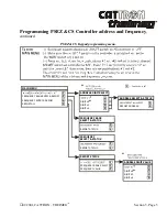
01/2001, CATTRON
- THEIMEG
TM
Section 4, Page 7
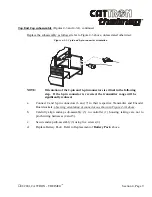
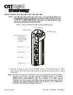
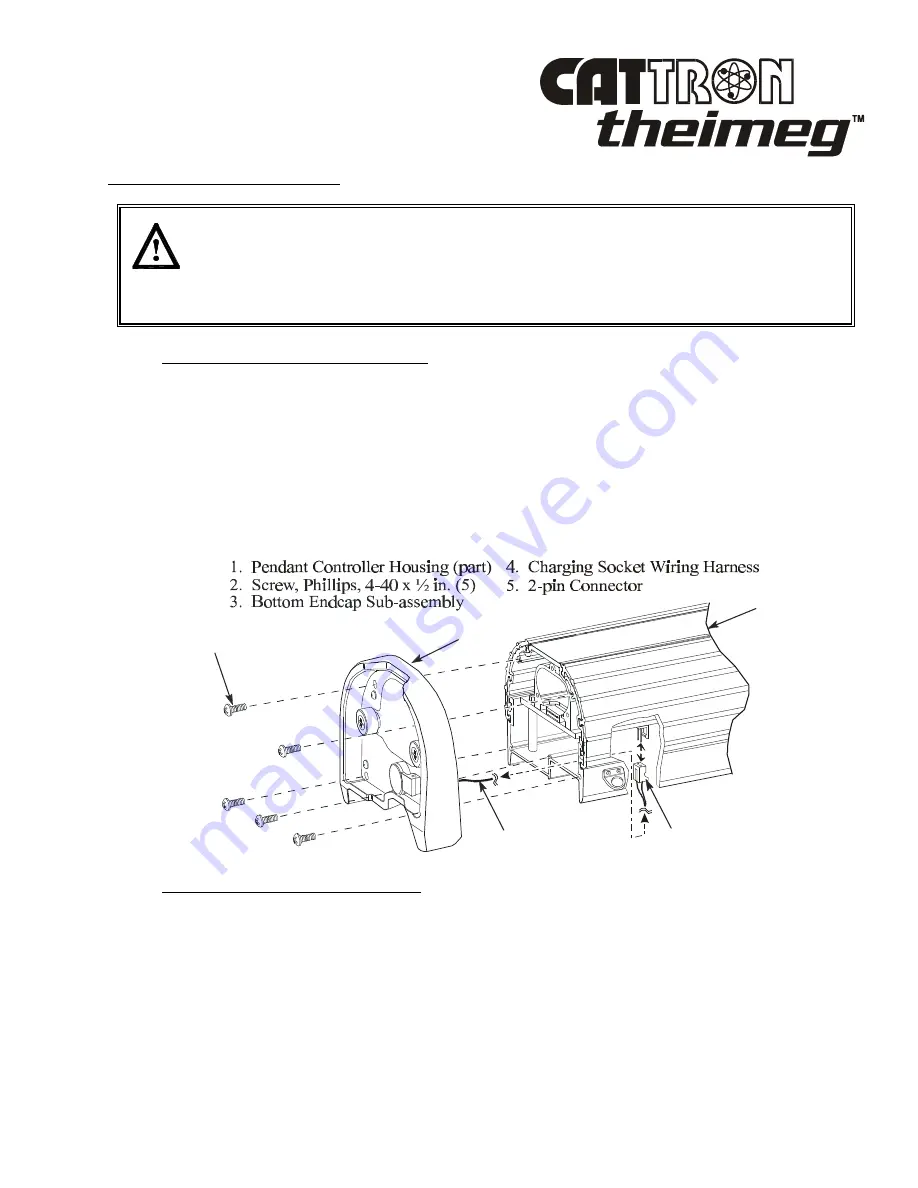
Bottom End Cap subassembly
(Figure 4-2).
CAUTION:
All circuit boards are sensitive to electrostatic discharge. Use an anti-static mat
and personal grounding strap (wrist) for all maintenance procedures involving
disassembly and assembly of PS controllers. Failure to comply with this caution
may result in equipment damage and will void our warranty.
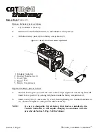
Remove the subassembly as follows:
a. Lay controller (1) face down on Anti-Static Mat and remove Battery Pack. Refer to
Removal of
Battery Pack
, above.
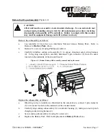
b. Remove five screws (2) using Phillips screwdriver.
c. Carefully withdraw endcap sub-assembly (3) to expose charging socket wiring harness
(4). Using long nosed pliers, carefully disconnect 2-pin connector (5) from its socket
located on the underside of the encoder board.
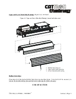
Figure 4-2. Bottom Endcap Sub-assembly, removal and replacement
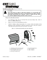
Replace the subassembly as follows:
a. Observing correct orientation as illustrated in the cutout above, connect 2-pin connector
(5) to its socket located on the underside of the encoder board.
b. Carefully align endcap subassembly (3) to controller housing (1), taking care not to pinch
charging socket wiring harness (4).
c. Secure endcap sub-assembly (3) using five screws (2).
d. Replace the Battery Pack. Refer to Replacement of
Battery Pack
, above.
5
4
2
1
3
Summary of Contents for i-Key
Page 2: ......
Page 14: ...Page xii 01 2001 CATTRON THEIMEG TM EZ CS AT Rx Rx Tx Tx Tx Rx Rx Rx ...
Page 20: ...Section 1 Page 6 01 2001 CATTRON THEIMEG TM This page intentionally left blank ...
Page 44: ...Section 4 Page 4 01 2001 CATTRON THEIMEG TM ...
Page 52: ...Section 4 Page 12 01 2001 CATTRON THEIMEG TM This page intentionally left blank ...
Page 68: ...Section 5 Page 16 01 2001 CATTRON THEIMEG TM This page intentionally left blank ...
Page 75: ... 01 2001 CATTRON THEIMEG TM Section 6 Page 7 Item 7 Carrying strap shoulder Part 42C 0057 ...
Page 89: ......


