background image

Cattron™ MP96/48 Series Portable Remote Control Systems 

User Manual 


50 

68C-MP96/48-RD-EN 
Version 006 

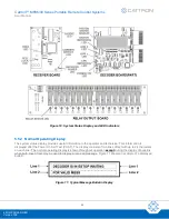
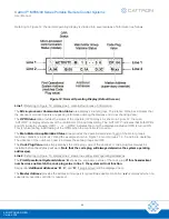
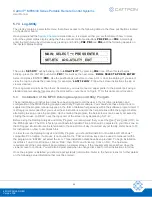
At certain times during operation, the address values shown on Line 2 will change temporarily (for approximately 
one second) to indicate specific activities or conditions of the system. In the example shown in Figure 12, the  

A: 04

’ indication may be replaced by any of the following activity codes: 

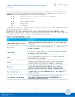
A: OL


ONLINE but not receiving messages (indicates address TIMEOUT) 

A: 

**


Default message received 

A: ++


Change message received 

A: >>


Scanner active 

EA


Invalid address 

In addition, lines 1 and 2 of the display may change temporarily to indicate received messages (Standard System 
Event Bulletins), as was shown in Figure 11. 

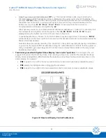
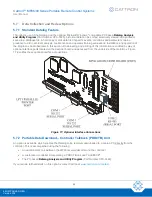
Additional LED indicators are located on the receiver board, decoder board and relay output board

Referring back to Figure 10, these LEDs also indicate system status and are particularly useful in troubleshooting 
and adjusting the receiver. Table 2 contains an explanation of the LED indicators. 

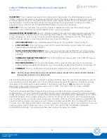
Table 2: LED Indicator Status Codes 

LED 

Description 

Relay Status (relay output board) 

The red Relay Status LEDs energize whenever the corresponding relay 
is energized. 

Receiver Power  

The red Receiver Power LED indicates the presence of DC power on the 
receiver circuit board. 

Carrier Detect 

The green Carrier Detect LED on the receiver circuit board indicates that 
the receiver is receiving a RF signal. 

Data 

The yellow Data LED on the receiver circuit board indicates that the 
message received contains data. 

Q-Sync 

The orange Q-Sync LED on the receiver circuit board indicates an 
interrupt that signifies the decoder has received a new message. 

VCO Lock 

The red VCO Lock LED is located on the receiver circuit board 
underneath the EMI/RFI shield. This LED lights when the receiver 
frequency synthesizer is able to lock onto the required frequency. 

Power ‘ON’ (decoder board) 

The green 

Power ‘ON’ LED indicates the presence of DC power on the 

decoder circuit board. 

CPU Watchdog (decoder board) 

The red CPU Watchdog LED indicates that the decoder board 
microcomputers are not decoding proper messages and, as a 
consequence, have been shut down. 

Summary of Contents for MP48 Series

Page 1: ...Cattron MP96 48 Series Portable Remote Control Systems User Manual 68C MP96 48 RD EN ...

Page 2: ...o non infringement nor as to the fitness merchantability or sustainability of any Cattron products for any specific or general uses Cattron Holdings Inc or any of its affiliates or agents shall not be liable for incidental or consequential damages of any kind All Cattron products are sold pursuant to the Terms and Conditions of Sale a copy of which will be furnished upon request When used as a tra...

Page 3: ... 4 Principle of Operation 18 4 5 System Functions 19 4 5 1 Fault Tolerant Operation 20 4 5 2 Protocol 20 4 5 3 Decoder Circuit Board 20 4 5 4 Multiple Microcomputers 20 4 5 5 System Initialization 21 4 5 6 Multiple Watchdog Circuits Hardware and Software 21 4 5 7 Automatic Safety Override ASO 21 4 5 8 System Status Display 22 4 5 9 Serial Communication Ports 22 4 6 Standard Datalog Feature 22 4 6 ...

Page 4: ...2 4 Disconnect and Outlet 38 5 2 5 Transfer Switch 38 5 2 6 Relay Outputs 39 5 2 7 R C Snubbing 39 5 2 8 Mainline Circuit Operate and Reset Relays 39 5 2 9 Attenuator 41 5 3 Installation 41 5 3 1 Getting Started 41 5 3 2 Choosing a Mounting Location 41 5 3 3 Wire Routing 42 5 3 4 Remote Antenna Location 43 5 3 5 Triple Diversity Antenna 44 5 3 6 Direct DC Wiring Option 44 5 4 Preset Frequency Sele...

Page 5: ...Maintenance 71 7 4 Typical Additional Checks 71 7 4 1 Primary Power Supply 71 7 4 2 Fuses 71 7 4 3 Fuse Holders 71 7 4 4 Unit Assemblies 71 7 4 5 Antenna System 72 7 4 6 Netting 72 7 5 Adjustments 72 7 6 Troubleshooting 73 7 7 System Status Display Codes 76 7 8 Displayed System Bulletins 77 7 9 Logged Bulletins 79 7 9 1 Standard Logged System Event Bulletins 79 7 9 2 Standard Logged System Receive...

Page 6: ...e Extend Setup 107 Scanner Setup 108 Attenuator Setup 109 Factory Preset and Field Programmable Frequencies 110 Factory Preset Default Frequencies 110 Field Programmable Frequencies 111 Appendix II Recommended Safety Rules for Portable Remote Controlled PRC Cranes 114 Preface 114 Operator Safety Basics 114 Area Inspection 114 Crane Inspection Mechanical and Structural 114 Operational Safety Check ...

Page 7: ...Cattron MP96 48 Series Portable Remote Control Systems User Manual 7 68C MP96 48 RD EN Version 006 Remote Controlled Crane Under Repair 119 Condition of the Remote Controlled Crane 120 ...

Page 8: ... specific address and frequency before leaving our factory Thus the address and frequency of the system controller is factory set to operate its corresponding MP Series receiver decoder Upon installation Cattron strongly advises you to check that our preconfigured address and frequency is not duplicated in other Cattron remote control equipment located at or around your operating facility This equ...

Page 9: ...detection routines OPR Operate CS Crane Specific PRC Portable Remote Control DC Direct Current PTO Push to Operate DOC Department of Communication RF Radio Frequency DP Dual Pressure RFI Radio Frequency Interference EDP Electronic Data Processing RSSI Receive Signal Strength Indication EEPROM Electrically Erasable Programmable Read Only Memory RST Reset Relay EMI Electro Magnetic Interference SP S...

Page 10: ... found on your Cattron Portable Remote Controller These symbols are intended to 1 convey information independently of language and 2 identify operator controls and functions LOW BATTERY ALARM HORN RESET STEP LESS PUSH BUTTON 2 STEP PUSH BUTTON 3 STEP PUSHBUTTON ACTUATE ONLY DURING OPERATION RECEIVE TRANSMIT TX RX ROTARY SELECTOR SWITCH ON OFF SWITCH STOP SWITCH ELECTRONIC i KEY A C A B ...

Page 11: ...ependability required for operating machinery in harsh industrial environments as the MP96 but with fewer features The bulk of the information in this manual applies to both the MP96 and the MP48 However as stated above the MP48 is equipped with fewer features than the MP96 Therefore we have provided a MP96 MP48 Feature Comparison of both products later in this manual ATTENTION We emphasize that s...

Page 12: ...HEREFORE IT SHOULD BE FULLY UNDERSTOOD THAT 1 WHEN A PRC SYSTEM HAS LEFT OUR FACTORY CATTRON HAS NO CONTROL OVER ANY ADDRESSES AND FREQUENCIES SUBSEQUENTLY ASSIGNED AND PROGRAMMED BY YOU OR BY OTHERS EITHER NOW OR IN THE FUTURE 2 CATTRON HAS NO CONTROL OVER THE ADDRESS AND FREQUENCY ASSIGNMENTS OF ANY OTHER PRC SYSTEM S THAT MAY BE IN OPERATION IN CLOSE PROXIMITY TO YOUR FACILITY CONSEQUENTLY AND ...

Page 13: ...OTE OPERATED CRANES OR CARRIERS AN AUDIBLE OR VISUAL WARNING MEANS SHALL BE PROVIDED IN ADDITION ALL EQUIPMENT SHALL HAVE AUDIO OR VISUAL ALARM INDICATIONS MEETING GOVERNMENTAL REQUIREMENTS WARNING WHEN INSTALLED TO YOUR CONTROLLER NEVER DISABLE THE PUSH TO OPERATE PTO BAR SWITCH WARNING DE ENERGIZE AND TAG OUT ALL SOURCES OF ELECTRICAL POWER BEFORE CARRYING OUT TOUCH TESTS ON EQUIPMENT FAILURE TO...

Page 14: ...NT IN A SAFE MANNER IT IS IMPERATIVE THAT YOU ARE PREPARED FOR AN UNPLANNED STOP OF THE EQUIPMENT AT ANY TIME AND DO NOT PLACE YOURSELF OR OTHERS IN A POSITION WHERE THIS SITUATION MAY CAUSE YOU TO FALL FROM THE EQUIPMENT FAILURE TO USE CAUTION MAY LEAD TO INJURY OR DEATH Cautions CAUTION ON 12 VDC APPLICATIONS INCOMING POWER MUST HAVE A 1 AMP SLOW BLOW FUSE IN LINE WITH THE POSITIVE LEAD NEAR THE...

Page 15: ...wer discharge and ground a circuit before touching it Adhere to all lock out tag out requirements DO NOT SERVICE OR ADJUST ALONE Whenever possible do not attempt internal service or adjustment of equipment unless another person capable of rendering aid and resuscitation is present FINGER RINGS JEWELRY Finger rings have caused many serious injuries Remove rings watches and other metallic objects wh...

Page 16: ...all three microcomputers communicate with each other when necessary providing a high degree of back up Taking the MP96 system as an example the control microcomputer receives incoming data that has been processed by the receiver It decodes the incoming data checking for all the correct addresses data and error check bytes The secondary microcomputer receives the same data as the control microcompu...

Page 17: ...central reference point The output interface is handled by solid state plug in relays rated for heavy duty resistive and inductive industrial loads Each output function relay has two screw terminals an output fuse and an LED indicator The output contact of each critical and directional output relay is also monitored by the decoder which is used to sense and verify each of these relay outputs Upon ...

Page 18: ...tput relays Antenna The connected antenna provides radio reception for the receiver decoder Three antennas may be installed in a triple diversity antenna configuration Power supply module The power supply module inside the Gold Box provides all required power for the receiver decoder This module also contains an over voltage under voltage board with factory pre programmed setpoints The power suppl...

Page 19: ...of OPR may be maintained for 10 minutes depending on system configuration 4 5 System Functions With the Cattron MP96 the average response time after a controller function switch is first operated and the output device is actuated is less than 60 milliseconds In jogging applications where a function switch is depressed for the second and consecutive times the average response time is less than 120 ...

Page 20: ...of a unique Cattron intelligent digital message protocol for industrial control applications rather than the customary Electronic Data Processing EDP type of message format Only the unique digital data message generated by a Cattron controller transmitter will be recognized all others are rejected This special protocol is complex and consists of start bits synchronization address command and error...

Page 21: ...Circuits Hardware and Software The MP96 decoder has hardware and software watchdog circuits designed to shut down the machine when conditions are not valid to allow continued operation These safety circuits ultimately disconnect output function relays motor mainline relays and the machine mainline relays OPR1 and OPR2 Hardware watchdogs are electronic component timers that will turn off if they ar...

Page 22: ... display please refer to the Installation section of this manual 4 5 9 Serial Communication Ports The Cattron MP96 system decoder is available with two RS 232 ports COM 1 and COM 3 and an isolated RS 485 port COM 2 The two RS232 ports are bi directional and are used for Datalog download via a Microsoft Windows compatible PC or laptop The isolated RS 485 port is used to communicate with external se...

Page 23: ...for this log is defined by Cattron engineers based on customer needs Eight different snapshot logs can be stored by the MP96 These logs are also FIFO based storage Each snapshot contains 32 snapshot events Some common examples of Snapshot Logs are Pitch activated Tilt activated Emergency brake activated 5 Totalizer Logs The totalizers are divided into three types of stored data One type of log can...

Page 24: ... as an option with the MP96 Datalog Analysis Utility Program This program has been developed in a universally understood format Microsoft Windows and enables the use of a PC to better manipulate view print and store the datalog information to provide a graphical representation of the datalog contents A demo disk set of this program Part Number 69C 0019D is available free of charge contact Cattron ...

Page 25: ...posable Alkaline battery packs are available Low Battery Warning and Battery Conservation All Cattron controllers employ an LED to provide a LOW BATTERY indication When transmitting with a good battery the LED will flash green Dependent upon the controller type a flashing red or amber LED will illuminate when approximately one hour of operation remains An automatic battery saver feature is standar...

Page 26: ...mmable receive frequencies in addition to the 16 factory pre programmed frequencies These frequencies are programmed using the receiver s pushbutton switches and Liquid Crystal Display LCD A user friendly interface guides the operator through the menus to where the field programmable frequency table is selected and frequency values are programmed The R2HN receiver also has two pushbuttons for prog...

Page 27: ... feature Scanner The optional Scanner function allows the receiver to automatically scan up to 16 factory or field programmed frequencies for signals from the controller Scanning is stopped on the desired channel by the MP96 decoder when it decodes the proper data address BCH auxiliary functions etc This feature can be used in multi controller applications where controllers operate on different fr...

Page 28: ... Under Voltage Trips 4 11 MP96G2 Decoder Board Field Programmable Memory EEPROM The Cattron MP96 system decoder has an Electrically Erasable Programmable Read Only Memory EEPROM Integrated Circuit IC that allows a limited amount of field changes to be made to the operation of the system If enabled by Cattron application engineers this memory device will store data that can be changed in the field ...

Page 29: ...continued limited operation during isolated failures Proportional volt free potentiometer equivalent outputs for proportional applications Optically isolated output modules allowing mixed control voltages EMI RFI shielded compartmentalized sub chassis no motherboard or card cage Several power supply options allowing operation from a wide variety of power sources Remote control techniques keypad to...

Page 30: ... x 610 mm x 203 mm Electronic Sub Chassis Gold Box Receiver decoder and power supply each have their own EMI RFI shielded compartment entire sub chassis mounts on inside door of NEMA 12 IP65 enclosure with four nuts allowing easy removal no relays in sub chassis Control Voltage Range 12 250 VAC or VDC at 0 55 5 A higher voltages with derated current Proportional Dry Potentiometer unipolar and bipo...

Page 31: ... MP96 48 Series Portable Remote Control Systems User Manual 31 68C MP96 48 RD EN Version 006 Note As part of our continuous improvement policy Cattron reserves the right to change Specifications without notice ...

Page 32: ...State Digitally Proportional Analog and Electromechanical interfacing capabilities YES YES Up to 48 inputs and 96 outputs allow for complete customization YES NO Up to 16 inputs and 48 outputs allow for complete customization YES YES Multiple operators may use a single frequency RF version only YES YES Long ride through time during power supply interruptions YES YES Optional Pitch and Catch featur...

Page 33: ...ES YES Simultaneous and independent data signal processing of all incoming commands by two separate micro controllers YES NO Two separate outputs for mainline control YES NO Extensive EMI RFI protection YES YES Can maintain safe control through brownouts power surges YES YES Complete system diagnostic test on power up YES YES Individually fused and isolated outputs YES YES Allows for low voltage p...

Page 34: ...tomated control system applications YES YES May be used as a stand alone machine control data collection or preventative maintenance tool YES NO ADDITIONAL FEATURES AND ADVANTAGES Multiple Watch Dog timers ensure that no motion is carried out without command total of five two hardware three software for CPU mainline and motor functions YES YES Compact EMI RFI single unit decoder chassis YES YES Pl...

Page 35: ...including Mainline ON OFF YES YES Enclosure NEMA 12 IP65 standard dust oil and watertight NEMA 4 and 4X IP66 optional YES YES Sub Chassis Receiver decoder and power supply each have their own electromagnetic compliant EMC shielded compartment entire sub chassis mounts on inside door of NEMA 12 IP65 enclosure no relays in sub chassis YES YES Dimensions Sub chassis Approximately 13 x 13 x 3 330 mm x...

Page 36: ...ume line of sight operation and are dependent on power frequency antenna and application YES YES Microcomputer Speed 11 095 MHz YES YES Memory Size Two E Proms each with 1 MB of memory programmed by Cattron YES NO Datalog Memory Size 64K bytes YES NO Optional Diagnostic Port RS232C DB25 Connector or RS422 MIA Connector YES NO Optional Bus Architecture serial port for Profibus Modbus etc YES NO ...

Page 37: ...d and issued Each relay on the relay output board is completely independent of all other relays There are no common connections between any output contacts This allows the connection of different power sources AC and DC to each of the separate relays The contacts are rated at 5 A 250 VAC or 5 A 30 VDC All contacts are individually fused with 250 V 5 A fuses All relays have a single Normally Open c...

Page 38: ...te or manual operation refer to the drawings provided with your system for interconnection details If a transfer switch is used it should be connected so that power is removed from the remote control system when the transfer switch is in the MANUAL position and vice versa The transfer switch provides an easy way to switch the controlled equipment from MANUAL to REMOTE control Installing the transf...

Page 39: ...ximum of six proportional volt free potentiometers are available in lieu of single ON OFF outputs 5 2 7 R C Snubbing R C snubbing circuits are provided on all relay outputs These snubbing circuits provide protection for each relay contact when it is connected to an inductive load Note On some high impedance loads such as PLCs or VFDs small leakage current approximately 200 µA at 115 VAC may presen...

Page 40: ...on energizes the mainline contactor Referring to Figure 5 an auxiliary function may be used as a Reset RST output that will only be effective when the Operate OPR relays have been closed Momentary closure of the Reset RST relay picks up the mainline ML contactor which is maintained under control of the OPRs Thus power is supplied to the controlled device If an OPR opens the mainline contactor rele...

Page 41: ...manual 5 3 Installation 5 3 1 Getting Started As previously instructed study the customized schematic drawings for your installation If there are any questions concerning the drawings or installation requirements contact Cattron at www cattron com contact before proceeding If any additions or corrections are made during the installation note the changes on the drawings in red ink Return the marked...

Page 42: ... practical spacing Shield each class of conductors in their own duct or conduit Use metal wire ducts conduits with a solid connection to earth ground Make conductors of different classifications cross each other at 90 degree angles Classifications Type I Communication lines including RS 232 and RS 485 TTL and other very low power DC control signals analog input and output signals Type II AC and DC...

Page 43: ...interference does not impact the system s performance Contact Cattron at www cattron com contact for more information or for help in resolving any problems Connect the BNC end of the coaxial cable to the BNC connector on the top of the receiver decoder electronic chassis Gold Box and the PL259 connector to the remote antenna mounting bracket Unless provided a hole must be cut in the bottom of the ...

Page 44: ...trolled machine in such a way that the operator can keep one antenna in the line of sight at all times For example mount one antenna on each of three corners of the controlled machine If this is not possible then mount the antennas so as to keep one in line of sight from as much of the work area as possible In addition we recommend that you physically tag each antenna and its associated line kit w...

Page 45: ...ternal DC filter between the power supply and the receiver decoder power terminals When the receiver decoder is supplied with DC voltage in this fashion the circuit breaker on the Gold Box is non functional If an ON OFF switch is required it must be provided in the power supply lines by the installer The installer provides all wiring switches fuses and terminals Referring to Figure 8 two screw ter...

Page 46: ...ng sheets supplied with the system for a list of the frequencies available on your receiver R2HN receivers and R3HNX transceivers also allow for field programming of 14 additional frequencies to any frequency desired between 447 MHz and 472 MHz IF ONE OF THESE RECEIVERS IS INSTALLED IN YOUR SYSTEM SKIP THE PROCEDURE OUTLINED IN THIS SECTION OF THE MANUAL AND REFER TO APPENDIX I R2HN Receiver FOR A...

Page 47: ...ing system power initialization Specific machine custom events or conditions identified by the customer and designed into the system engineering e g low air pressure input Normal internal events of the MP96 electronic components and software operation Hardware related failures that may occur on the decoder board Incoming data messages and bit errors that may occur due to transmission problems Inte...

Page 48: ...on to the operator and technician This information is displayed after the Power On Self Test POST The display consists of two lines of text with up to 24 characters on each line The normal operating display is shown throughout operation except during the display of bulletins when both lines of text may be used to display a received message Figure 11 shows an example of a displayed bulletin Figure ...

Page 49: ...ng initial testing of the OPRs when the controller is turned on The Main Motor Group Mainline Status area provides the operational status of each of the motor group s mainline contactors up to six Using the example shown in Figure 12 motor groups 1 2 5 and 6 are operating The absence of the numbers 3 and 4 indicates those two groups are OFF The Code Plug Value area simply displays the code plug va...

Page 50: ...explanation of the LED indicators Table 2 LED Indicator Status Codes LED Description Relay Status relay output board The red Relay Status LEDs energize whenever the corresponding relay is energized Receiver Power The red Receiver Power LED indicates the presence of DC power on the receiver circuit board Carrier Detect The green Carrier Detect LED on the receiver circuit board indicates that the re...

Page 51: ...two systems should share the same address even if they are on different frequencies The crane or controlled machine must be equipped with the proper braking devices If a fault occurs in the remote control system the Operate OPR relays will de energize The machine must be capable of stopping if this happens or if a loss of power occurs Before applying power to the receiver decoder verify the correc...

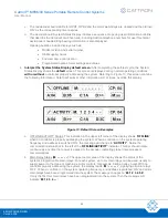
Page 52: ...er information will at times override this display Figure 13 Default Screen Examples a OFFLINE ACTIVITY Status This indication in the upper left corner of the display shows OFFLINE when no controller is properly addressing the system When a controller on the system operating frequency and address is switched ON the message will change to ACTIVITY Notice the communication status bar to the left of ...

Page 53: ...programmed For example M 0A will be displayed in the lower right hand corner when this hexadecimal code has been selected as the Master Override address Note that when the decoder is waiting for a controller on the system operating frequency and address to go on line the symbols will alternate among the valid addresses to indicate that the system is idling In addition all output relays are OFF at ...

Page 54: ...in steps i and ii above to set the minutes seconds day month and year iv When you have finished use PB2 or PB4 to highlight EXIT and press PB3 to select it 6 Check for Controller power up and correct receiver decoder response The controller and receiver decoder must have identical frequencies and address codes This information is normally found on the controller model ID tag in the battery compart...

Page 55: ...ted indicating regulated operating voltage is present at the decoder board d Referring to Figure 15 observe the Operate outputs OPR1 OPR2 on the second row output relay interface board positions 0 and 1 respectively The red LEDs associated with these relays should be illuminated Observe the main outputs at positions 2 3 4 13 14 and 15 if all six are programmed those LEDs should also be illuminated...

Page 56: ...em and demonstrates that when a signal is lost or interrupted all output relays will immediately return to the OFF condition It should be noted that on non licensed systems the OPR relays will remain energized for 10 minutes For non licensed systems only restore power to the controller Activate and maintain a function switch on the controller While holding the function switch observe the relays on...

Page 57: ... electronics chassis to the relay outputs for that motor which should disable the motor on the machine The system status display posts an error bulletin showing the failed output including the disabled main relay and matrix outputs The remaining machine motors are still enabled allowing the operator to finish any critical operations move the machine load to a safe position and troubleshoot the fai...

Page 58: ...c Referring to Figure 16 open the receiver decoder door and touch one end of a Test Jumper to TB2 Terminal 1 Touch the other end of the test jumper to TB1 Terminal 2 This will energize the ACTIVITY Input The system status display will post a system shutdown bulletin because the mainline was energized without command Figure 16 Input and Output Relay Interface Boards ASO Test Points Apply power to t...

Page 59: ... energize and Stage 2 shutdown occurs OPR1 OPR2 all main and all function outputs will be disabled The system status display will post a system shutdown bulletin because the function was energized without a command i Remove the Test Jumper and press the Reset PushButton PB1 on the decoder to clear the fault j Repeat steps i thru l above for each of the remaining motor directional relay outputs ide...

Page 60: ...scribed later in this section Downloading and printing of this information is enabled by way of optional interface ports located on the decoder board and accessed from the underside of the Gold Box Figure 17 identifies these optional interface connections Figure 17 Optional Interface Connections 5 7 2 Portable Data Download Controller Talkback PDDCTB Unit An option is available which enables the D...

Page 61: ...Cattron MP96 48 Series Portable Remote Control Systems User Manual 61 68C MP96 48 RD EN Version 006 ...

Page 62: ...ou should use these instructions to supplement the program manual supplied in the form of detailed help screens within the software program itself It is strongly recommended that you review these instructions and also the help screens within the program before attempting to setup or use the program Upon entering the program the help screens can be easily accessed by clicking the mouse on HELP near...

Page 63: ... If the PDDCTB was not ordered enter 448 1000 DECODER ADDRESS This must be the address of the system decoder which can be found in the drawing package supplied with the system or on the serial tag applied to the Gold Box for example 01 COMMENT This is an optional item for any pertinent comments the user deems necessary Note All of the above information must be completed accurately except for the c...

Page 64: ... LIST DATALOG FILES TO VIEW IN CURRENT UNIT Select the most recent and click on OK Note Each time a particular MP96 datalog is downloaded the program automatically increases the filename extension by 001 For example the first time system serial 5500011 is downloaded the log filename created is 5500011 001 The next time that same system is downloaded the log filename created is 5500011 002 and so o...

Page 65: ...ovide general guidelines for remote control operation of equipment and should not be used as a substitute for your plant operating procedures 1 Before operating equipment carry out the following a Ensure the address code and frequency of your remote controller exactly matches the address code and frequency of the target equipment to be operated The address and frequency assigned to your controller...

Page 66: ...operation until fully repaired 3 If anyone is in the path of equipment travel stop and sound the alarm before proceeding Do not proceed until the path is clear 4 Persons operating this equipment shall not use a limit stop as a utility stopping device 5 When leaving the equipment area for any reason set the controller s Power ON OFF Switch es to the OFF position If a Key Switch is installed remove ...

Page 67: ...must be set to ON for power to be applied to the controller b Set the controller s Power ON OFF Switch es to the ON position When transmitting with a good battery two short beeps will be heard immediately after the Power ON OFF Switch is set to ON and a green TRANSMIT LED will flash rhythmically When the battery starts to go low the green LED changes to a red or yellow depending on the type of con...

Page 68: ... the controller s Power ON OFF Switch es to the OFF position If a Key Switch is installed remove the key from the controller and keep it on your person 6 4 Operator Pitch and Catch Optional Pitch and catch is the operation of a single controlled machine or crane by two three or four operators on a first come first served basis This method provides lock out of the non commanding operator s and allo...

Page 69: ...r to ON and is ready to take control of the crane If Controller B is transmitting the correct system identification address Operator B is allowed to take control catch Operator A is now denied control access and should switch his her controller power to OFF 2 The second way to transfer control from Operator A to Operator B is to simply turn Controller A power to OFF for a designated period of time...

Page 70: ...stem from functioning As a result the maintenance program needs to include all of these components 7 2 Corrective Maintenance When performing corrective maintenance observe the following guidelines Tag all leads prior to desoldering or removal from a terminal board Use small wire tags or pieces of adhesive tape with handwritten numbers Reconnect all wires to the same location from which they were ...

Page 71: ...ower Supply Primary power sources should be the first step in performing preventive maintenance as they are always suspect in problems dealing with AC circuits The supply voltages can often be too high as well as too low Loose connections on fuses can occur even on an AC system With the system de energized check for hot fuses and connections 7 4 2 Fuses Fuses sometimes even when new may have too h...

Page 72: ...ver s green Carrier Detect LED will turn on If the carrier signal contains data and a Q Sync pulse as would be the case if the signal had been transmitted from a Cattron controller the receiver s orange Data LED and yellow Q Sync LED would also turn on In actual operation these three LEDs will flash rhythmically with each transmission of the controller This can be easily seen by observing the gree...

Page 73: ...ecoder No lights on receiver Loss of AC input power Bad circuit breaker Faulty power supply Check for 110 VAC or system operating power on input terminals in receiver decoder Check circuit breaker Replace faulty circuit breaker Check for 13 5 VDC output from power supply If 13 5 VDC is not detected on power supply output terminals replace power supply Power on at receiver but no power at decoder F...

Page 74: ... controller s address box in line 2 shows the code EA when a function is commanded the addresses for the controller and decoder do not match Check the address code displayed during the decoder power up sequence If the address is not correct replace the code plug Refer to the Code Plug Replacement procedure later in this manual for information on setting the address and replacing the code plug If t...

Page 75: ...ction is activated inspect the wiring and associated fuse Replace the relay as described in the Relay Replacement procedure later in this manual Mainline contactor picks up but certain output functions do not work Controller is not sending a command Controller is defective Faulty decoder relay board or ribbon cable Faulty wiring no power to device being controlled If the controller is equipped wit...

Page 76: ...It may be necessary to change the operating frequency of the remote control system Note that this message will be frequently displayed when timesharing the control frequency with another RF system In this case the message is normal and it is not an error EA The receiver has received a message with a bad address This message is normal in timesharing situations where multiple systems use the same fr...

Page 77: ... a system bulletin is present with a higher priority Figure 19 Standard Operating Display Default Screen Figure 20 shows a typical example of a displayed system bulletin Figure 20 Typical Displayed System Bulletin Depending on the configuration of your remote control system some or all of the bulletins shown in Table 5 may be displayed during normal system operation Note that every time a bulletin...

Page 78: ...ONBOARD MAIN1 MAIN6 OUTPUTS ENABLE FAILED ONBOARD OPR1 OUTPUT FAILED ACTIVITY ON OPR1 OFF OPR2 OUTPUT FAILED ACTIVITY ON OPR2 OFF LOOP FAULT ACTIVITY OFF WHEN OPR1 OPR2 ON ASO FAULT ACTIVITY ON WHEN OPR1 OPR2 OFF CODEPLUG VALUE INVALID CHECK CODEPLUG INTER PROCESSOR COMMUNICATIONS FAULT RAM CHECK FAULT CONTROL PROCESSOR RAM CHECK FAULT DATA PROCESSOR FAULT ASO STAGE 2 HAS BEEN REACHED PC DATALOG D...

Page 79: ...me system event bulletins may also be displayed during normal system operation refer to the section on Displayed System Bulletins Some or all of the bulletins shown in Table 6 may be displayed Table 6 Standard Logged System Event Bulletins Display Line 1 Display Line 2 OPR1 OUTPUT ON CONTROL PROC ONLINE OPR1 OUTPUT OFF CONTROL PROC OFFLINE OPR2 OUTPUT ON SECONDARY PROC ONLINE OPR2 OUTPUT OFF SECON...

Page 80: ...ER ADDRESS XMITTER IS OFFLINE MASTER ADDRESS ACTIVITY INPUT ON OPR1 OPR2 OUTPUTS ON ACTIVITY INPUT OFF OPR1 OR OPR2 OUTPUT OFF MESSAGE RX D FROM ADDRESS A MESSAGE RX D FROM ADDRESS B MESSAGE RX D FROM ADDRESS C MESSAGE RX D FROM ADDRESS D MESSAGE RX D FROM MASTER ADDRESS MAIN1 OUTPUT ON MAIN1 OUTPUTS ENABLED MAIN1 OUTPUT OFF MAIN1 OUTPUTS DISABLED MAIN2 OUTPUT ON MAIN2 OUTPUTS ENABLED MAIN2 OUTPUT...

Page 81: ... OPR1 OUTPUT ENABLE FAILED ONBOARD OPR2 OUTPUT ENABLE FAILED ONBOARD MAIN1 MAIN6 OUTPUTS ENABLE FAILED ONBOARD OPR1 OUTPUT FAILED ACTIVITY ON OPR1 OFF OPR2 OUTPUT FAILED ACTIVITY ON OPR2 OFF LOOP FAULT ACTIVITY OFF WHEN OPR1 OPR2 ON ASO FAULT ACTIVITY ON WHEN OPR1 OPR2 OFF CODEPLUG VALUE INVALID CHECK CODEPLUG INTER PROCESSOR COMMUNICATIONS FAULT RAM CHECK FAULT CONTROL PROCESSOR RAM CHECK FAULT D...

Page 82: ...ller and receiver decoder As well as being logged some system received message bulletins may also be displayed during normal system operation refer to the section on Displayed System Bulletins Some or all of the bulletins shown in Table 7 may be displayed Table 7 Standard Logged System Received Message Bulletins Display Line 1 Display Line 2 REQUEST TO SEND A TALKBACK RX D XMITTED DATALOG CLEAR HA...

Page 83: ...gged ASO FAULT Bulletins All critical outputs are monitored by ASO If any critical output fails ON without operator command that fault is logged into the datalog As well as being logged some ASO FAULT bulletins may be displayed during normal system operation refer to the section on Displayed System Bulletins Application specific ASO FAULT Bulletin descriptions are chosen by Cattron when engineerin...

Page 84: ... refer to the section on Displayed System Bulletins Some examples are MAGNET TEMPERATURE HIGH SET LOAD AND REPAIR HYDRAULIC BRAKE SYSTEM PRESSURE IS TOO LOW 7 10 Receiver Decoder Repair 7 10 1 Replacing the Electronics Chassis Gold Box Replacing the Electronics Chassis or Gold Box with a spare unit is the easiest and fastest way of correcting problems with the receiver decoder The Gold Box can the...

Page 85: ...ts corresponding decoder board edge connector 10 Connect the antenna BNC connector s to their socket s on top of the Gold Box 11 Connect the power input plug to the main power supply 12 Compare the frequency and address code for the new Gold Box to the frequency and address code of the old Gold Box When applicable set the frequency as described in Preset Frequency Selections Model R1HN Receiver On...

Page 86: ...erring back to Figure 21 replace a relay interface board as follows 1 Open the cover of the receiver decoder enclosure 2 Remove power from the Gold Box by turning off the circuit breaker on the bottom 3 Disconnect the power input plug from the main power supply 4 Disconnect the ribbon cable header at the relay interface board Note Tag and record the individual wire locations before removing the wi...

Page 87: ...eiver The EPROM determines the frequency bank and contains the program for the receiver Note and record the part number on the label of the EPROM before replacing the receiver board If the existing EPROM part number does not match the EPROM part number on the replacement receiver board contact Cattron at www cattron com contact Referring to Figure 22 replace the receiver circuit board as follows 1...

Page 88: ... Box and secure by tightening the four captive screws 13 Restore power to the receiver decoder by turning on the circuit breaker on the bottom of the Gold Box 14 Close the cover of the receiver decoder 15 Perform a functional check of the PRC System refer to the System Checkout section of this manual Figure 22 Receiver Replacement ...

Page 89: ...ntact Cattron at www cattron com contact When swapping out or installing an EPROM refer to the EPROM Replacement procedure found later in this manual Referring to Figure 23 replace the decoder circuit board as follows 1 Open the cover of the receiver decoder enclosure 2 Remove power from the electronics chassis or Gold Box by turning off the circuit breaker on the bottom 3 Disconnect the ribbon ca...

Page 90: ...ug from the old decoder circuit board in the same fashion Install the code plug in the new circuit board 12 Install the lid on the Gold Box and secure using the four captive screws 13 Restore power to the receiver decoder by turning on the circuit breaker on the bottom of the Gold Box 14 Close the cover of the receiver decoder 15 Perform a functional check of the PRC System refer to the System Che...

Page 91: ...ory If the code must be changed a new code plug with the new code must be obtained from Cattron In some circumstances Cattron may provide blank or unset code plugs An unset code plug must have a code set prior to installing in the decoder This is described in the procedure below Installing an unset code plug will produce an error code and the receiver decoder will not operate To replace the code p...

Page 92: ...Cattron MP96 48 Series Portable Remote Control Systems User Manual 92 68C MP96 48 RD EN Version 006 Figure 24 Code Plug Settings ...

Page 93: ...receiver decoder by turning on the circuit breaker on the bottom of the Gold Box 10 Close the cover of the receiver decoder 11 Perform a functional check of the PRC System refer to the System Checkout section of this manual 12 Return the EPROM to Cattron 7 10 8 Power Supply Module Replacement Referring to Figure 25 replace the power supply module as follows 1 Open the cover of the receiver decoder...

Page 94: ...nput plug to the main power supply 11 Restore power to the receiver decoder by turning on the circuit breaker on the bottom of the Gold Box 12 Close the cover of the receiver decoder 13 Perform a functional check of the PRC System refer to the System Checkout section of this manual Figure 25 Power Supply Module Replacement ...

Page 95: ...erial number This will enable our engineers to access your system configuration and provide a quick response 8 2 Accessories When your MP96 48 Series Portable Remote Control PRC system is used in Electric Overhead Traveling EOT crane applications a popular accessory is described in the Two step Electro Hydraulic Brake Package section of this manual In addition we emphasize that a Transfer Switch w...

Page 96: ... emergency Brake pressure is stored using a hydraulic accumulator Any loss of power automatically results in application of the crane brake This provides braking even when crane power is lost or turned off for a short period of time For more information on our Two Step Electro Hydraulic Brake Package please contact Cattron at www cattron com contact 8 2 2 Transfer Switch Schematic A schematic diag...

Page 97: ...table Remote Control Systems User Manual 97 68C MP96 48 RD EN Version 006 9 Technical Support For remote and communication control systems support parts and repair or technical support visit us online at www cattron com contact ...

Page 98: ...www cattron com contact Attenuator Field Programmable Frequency Selection Close Start Range Limit and Range Extend require the use of a Triple Diversity Antenna system When installing a triple diversity antenna system we recommend that you physically tag each antenna and its associated line kit with a number 1 2 and 3 and permanently record its individual location on the controlled machine Such id...

Page 99: ... to visually observe all machine control functions Once the operator is within a preset programmable operating range of the machine he or she will be required to unlock the Close Start function before being allowed to proceed with remote control operations There are three parameters you will be required to set Time determine the time the operator can be off the air before remote control operation ...

Page 100: ...s on the receiver Close Start utilizes RF signal strength to determine the close start distance and therefore is not a precise setting Many factors may affect the RF signal strength such as controller position antenna position and direction building environment and background RF noise After setting Close Start check the system performance several times You may have to repeat the setup procedure to...

Page 101: ...Cattron MP96 48 Series Portable Remote Control Systems User Manual 101 68C MP96 48 RD EN Version 006 Figure 27 Close Start Ranges ...

Page 102: ...controller Note 1 If FCC Part 90 requirements apply to your PRC system the controller will transmit a continuous RF signal once power is applied 2 If FCC Part 15 requirements apply to your PRC system you must also activate and maintain a controller function that will not cause any movement of the controlled machine This function could be a horn light or other indicator and must be maintained until...

Page 103: ...RSSI level is the strength of the RF signal received from the controller which should be transmitting or the background noise level if no signal is being broadcast The Set value is the signal strength limit for three consecutive controller transmissions with the same address for the receiver to unlock In the above example the signal strength must be at least 70dBm for three consecutive controller ...

Page 104: ...ng mode This requires the operator to move closer to one of the antennas to reduce intermittent operation at the extremes of the range limit perimeter Range Limit is not a precise feature as many factors may affect the setting such as controller position antenna position and direction building environment floor obstructions and background RF noise See Figure 28 for a pictorial representation of th...

Page 105: ...ignal from the transmitter Figure 28 Range Limit Operation 6 Press both display control pushbuttons on the receiver until the following message is shown on the LCD display PROGRAM OPTIONS MODE It should be noted that all remote control functions on the controlled machine are disabled any time the PROGRAM OPTIONS MODE is selected on the receiver Therefore activating a controller function will not c...

Page 106: ... change the Range Limit status A display of a number enables the Range Limit option The setpoint can be set to any value between 50 dBm and 126 dBm In this example attempting to set a value below 120 dBm will enable the Range Extend option and change the display to EXT Setting a value higher than 50 dBm disables the Range Limit and changes the display to OFF Remember that 117 dBm is a stronger sig...

Page 107: ...should be noted that all remote control functions on the controlled machine are disabled any time the PROGRAM OPTIONS MODE is selected on the receiver Therefore activating a controller function will not cause any machine movement Release both buttons The display will now change to show one of the other options that may be set for this receiver 5 Momentarily press and release both display control b...

Page 108: ...l the following message appears on the display SCANNER MODE IS TURNED OFF The display above shows the Scanner option disabled 6 Press and release either button to toggle the Scanner mode on and off 7 Once the desired Scanner status is set press and hold both display control buttons for approximately three seconds The status will be saved and the receiver will cycle through its power up self check ...

Page 109: ...ecessary To obtain an external attenuator for your receiver decoder contact Cattron at www cattron com contact To set the built in attenuator on the Model R2HN receiver perform the following procedure 1 As a safety precaution set the remote controller s power to OFF and remove power to all controlled machine motors before boarding the controlled machine 2 Board the controlled machine open the rece...

Page 110: ...ler that operates on a frequency that has not been preset at the factory or when other sources systems are emitting RF signals that interfere with safe operation Prior to making any change in the frequency setting check the frequency settings on both the receiver decoder and the controller To change the frequency setting for the controller refer to the documentation provided with the controller Th...

Page 111: ...ntrolled machine motors Field Programmable Frequencies Select and program the field programmable frequencies as follows 1 As a safety precaution set the remote controller s power to OFF and remove power to all controlled machine motors before boarding the controlled machine 2 Board the controlled machine open the receiver decoder door and remove the lid from the electronics chassis or Gold Box 3 S...

Page 112: ... for the frequency to be changed repeating steps 7 through 10 for each new frequency to be set 11 Press and hold both display control buttons for approximately three seconds to exit the options menu The receiver decoder will then cycle through the power up self check 12 Press both display control pushbuttons on the receiver until the following message is shown on the LCD display PROGRAM OPTIONS MO...

Page 113: ...le Remote Control Systems User Manual 113 68C MP96 48 RD EN Version 006 17 As required set the Gold Box power to OFF replace the lid close the cover of the receiver decoder enclosure and apply power to the controlled machine motors ...

Page 114: ... are operational in Portable Remote Control PRC mode by Radio Frequency If a crane is operated from cab or pendant control the PRC system s controller s should be completely isolated by removing the battery and held under lock and key A routine pre shift inspection of the crane takes a lot less time than repairing a crane suffering from a major problem In addition such pre shift inspections are to...

Page 115: ...ns of damage and shall be in perfect working order Operational Safety Check As a crane operator you should satisfy yourself of the following If any item below does not meet the checklist criteria immediately notify your supervisor In many cases the problem will need to be fixed before you are allowed to operate the crane Remember that the person now reading these instructions is primarily responsi...

Page 116: ...RC crane operator s movement These aisles should be a minimum of 3 ft 1 m wide or per local regulations PRC crane operators shall always position themselves in a safe location with the best view of the crane they are controlling and never operate the crane blindly They shall always keep the crane and load in sight staying as close as practical to the crane load while maintaining a safe distance ou...

Page 117: ...centered directly over the load to prevent load swinging when the load is raised Side pulls shall be made only with the permission and under the direct supervision of management When such a lift is being made operators shall not position themselves in the line or path of travel of the load but shall operate the crane from a position to the side opposite to the path of travel When raising or loweri...

Page 118: ...set Boarding the Remote Controlled Crane The PRC crane shall not be boarded without permission of the supervisor in charge of crane operations in the area Using the power ON OFF switch es the person boarding the PRC crane shall switch the portable remote controller to OFF and take it with him or her onto the crane When the controller is equipped with a STOP button this shall be set to the STOP pos...

Page 119: ...nformed of the repair work thoroughly instructed as to what their conduct should be for the duration of said repairs and informed when repairs are completed When there is a runway adjacent to the runway on which the crane is being repaired and if any hazard exists that involves the repairmen red lights shall be placed in clear view of persons traveling on the adjacent runway to indicate the restri...

Page 120: ...istortion Broken cracked or chipped rails on bridge or runway Condition and security of trolley and bridge rail end stops missing or damaged from impact Condition of all limit switches Conditions of controls electrical or mechanical defects that may lead to faulty operation Condition of electric motors carbon dust around inspection covers indicates worn brushes Condition of gears grinding or squea...

Page 121: ...duct improvement the information provided in this document is subject to change without notice Cattron Wireless Automation and Control Solutions Support For remote and communication control systems support parts and repair or technical support visit us online at www cattron com contact Cattron North America Inc 655 N River Rd NW Suite A Warren OH 44483 ...

Reviews: