Cattron™ MP96/48 Series Portable Remote Control Systems
User Manual
86
68C-MP96/48-RD-EN
Version 006
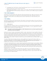
7.10.2 Relay Replacement
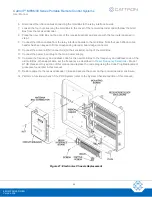
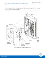
Referring back to Figure 21, replace a relay as follows:
1. Open the cover of the receiver/decoder enclosure.
2. Remove power from the receiver/decoder by turning off the circuit breaker located on the bottom of the
‘Gold Box’.
3. Release the captive screw and carefully withdraw the relay from the relay interface board.
4. Verify that the replacement relay is the same type as the relay removed.
5. Install the new relay on the relay output board, ensuring the relay orientation matches the orientation of
the other relays installed on the interface board.
6. Secure the relay in position by tightening the captive screw.
7. If desired, restore power to the receiver/decoder by turning on the circuit breaker underneath the Gold
Box.
8. Close and fasten the cover of the receiver/decoder enclosure.
9. As necessary, perform a functional check of the PRC System (refer to the System Checkout section of
this manual).
7.10.3 Relay Interface Board Replacement
Referring back to Figure 21, replace a relay interface board as follows:
1. Open the cover of the receiver/decoder enclosure.
2. Remove power from the Gold Box by turning off the circuit breaker on the bottom.
3. Disconnect the power input plug from the main power supply.
4. Disconnect the ribbon cable header at the relay interface board.
Note:
Tag and record the individual wire locations before removing the wires in the next step.
5. Disconnect all wiring from the terminal strip located on top of the relay interface board.
6. Remove the five screws securing the relay interface board to the pillars of the enclosure back panel.
Withdraw the interface board.
Note:
Tag and record the individual relay locations on the removed interface board before removing
the relays in the next step.
7. Withdraw the relay interface board and remove all of the relays
– refer to the Relay Replacement
procedure previously described.
8. Install the relays to the new interface board. Ensure each relay is in the correct location, as previously
tagged and recorded.
9. Install the new interface board and secure using the five screws.
10. Re-connect all wiring to the terminal strip located on top of the relay interface board. Ensure each wire is
in the correct location, as previously tagged and recorded.

