Cattron™ MP96/48 Series Portable Remote Control Systems
User Manual
38
68C-MP96/48-RD-EN
Version 006
Using a separate control transformer helps by reducing chances of a power slump if other electrical components
connected to it fail. It can also be sized to allow installation of a utility outlet near the receiver/decoder for
connection of a light or test equipment.
5.2.4 Disconnect and Outlet
The receiver/decoder requires less than 1 A at 115 VAC to operate
– refer to the drawings provided with your
system for interconnection details. A larger 10 A circuit is recommended to allow installation of a utility outlet
nearby for a light and test equipment. A fused disconnect switch provided by the installer should be installed as
close to the power source as possible.
5.2.5 Transfer Switch
If the equipment is to be operated in the
remote only
mode and there are
no manual controls
, the Transfer
Switch (TS) can be omitted. Otherwise, installation of a transfer switch is desirable to allow selection between
remote
or
manual
operation
– refer to the drawings provided with your system for interconnection details. If a
transfer switch is used, it should be connected so that power is removed from the remote control system when the
transfer switch is in the ‘MANUAL’ position and vice versa.
The transfer switch provides an easy way to switch the control
led equipment from ‘MANUAL’ to ‘REMOTE’
control. Installing the transfer switch may require changes to the controlled equipment wiring. Prior to changing
any existing wiring, create a wiring diagram of the planned changes. Use existing empty terminals on terminal
boards as tie points.
When the transfer switch is in the ‘REMOTE’ position, the manual controls should be disconnected and vice
versa. All power should be transferred to the radio control relays. When the transfer switch is placed in the
‘MANUAL’ position, manual control of the equipment should be restored. The equipment may now be controlled
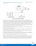
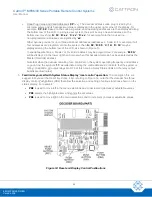
as it was prior to installation of the radio controls. Figure 3 shows a typical transfer switch wiring setup. The
transfer switch also contains an ‘OFF’ position. In this position all circuits are disconnected from both remote and
manual controls.
Figure 3: Typical Transfer Switch Wiring


