Remtron
®
Engineered Systems
User Manual
39
9M02-9028-A021-EN
Version 4.0
7.5
Receiver Troubleshooting
7.5.1 General
, and
Error! Reference source not found.
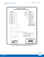
for the receiver layouts.
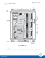
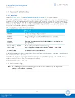
The 21R14A, 21R22, and the 22R08A have diagnostic LEDs plus a LED for each output relay to aid in isolating a
problem if one occurs. The 22R08A and 21R14A receivers have ‘OUTPUT’, ‘SIGNAL’ and ‘POWER’ diagnostic
LEDs on the front of the receiver case. The 21R14A and 22R08A series use a single circuit board for the receiver
and decoder. The 21R22 receiver has ‘SIGNAL’ and ‘POWER’ diagnostic LEDs on the front of the receiver case
and it uses a RF/Decoder board and a Relay board.
The following table describes the diagnostic LEDs.
LED
Indication
POWER
Receiver operating voltage is present
SIGNAL
OUTPUT
A signal is being received that matches the decoder’s address
SIGNAL
OUTPUT
Also, may indicate scanning mode in receivers with scanning function
(except 21R22)
SCAN 1 through SCAN 3
(21R22 only)
These LEDs cycle while receiver is scanning
When on steady, indicates which frequency receiver is locked onto
K1 through Kxx
Corresponding relays are energized
When the 21R22 is not receiving a valid signal, an OFF relay pulls in, which ensures that power is removed from
the mainline contactor on the crane.
When the receiver is receiving a signal in normal operating mode, the OPR relay drops out and the MLC relay
pulls in, allowing the main contactor on the crane to energize.
Note the 21R14A uses one MLC relay.
7.6
Receiver Testing
Note:
Before testing, we recommend isolating power to the crane and that all tag/lockout procedures
applicable to your facility are applied.

