Remtron
®
Engineered Systems
User Manual
27
9M02-9028-A021-EN
Version 4.0
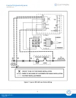
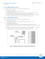
6.5.2 21R14A Installation Testing
Before putting the system into service, perform the following testing procedure:
1. Apply power to the receiver.
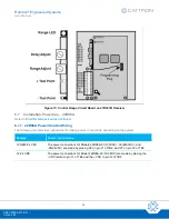
2. Verify that the POWER LED turns ON. Refer to
3.
Turn the transmitter to ‘ON’.
4. Verify that the K16 and Output LED turn ON; while the alarm is on, verify the Signal LED flashes.
5. Verify that voltage is present at the receiver normally open on output for the MLC.
6. Verify that no voltage is present at any of the relay output terminals that are used for your application.
7. If voltage is present at any output terminal that is used, recheck the system wiring.
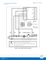
6.5.3 21R22 Installation Testing
Before putting the system into service, perform the following testing procedure:
1. Apply power to the receiver.
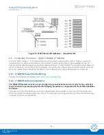
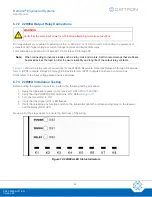
2. Verify that the POWER LED and the K23 (MLC) LED both turn ON. Refer to
3. Turn the transmitter
to ‘ON’.
4. Verify that the K23 LED turns OFF.
5. Verify that the K24 (OPR) LED turns ON and the SIGNAL LED FLASHES. Refer to
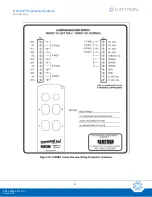
6. Verify that voltage is present between the receiver output and the Main Line Contactor (MLC) terminal 4
of TB4.
7. Verify that no voltage is present at any of the relay output terminals that are used for your application.
8. If voltage is present at any output terminal that is used, recheck the system wiring.
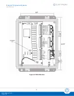
Figure 10: 21R22 Status LED Indicators
– Receiver ON (Transmitter OFF)


