background image

M

M

G

G

C

C

6

6

0

0

5

5

0

0

F

F


U

U

s

s

e

e

r

r

s

s


G

G

u

u

i

i

d

d

e

e


Rev.1.0 (Dec.2013) 

12


Not used 


Not used 


RxD (Connect to TxD of the other end) 

For debugging & factory use only.


TxD (RxD (Connect to RxD of the other end)) 

Ground of RS-232C 


ALARM IN/OUT and Composite Video Output 


Figure  2-3 

Terminal  block  for  the  I/O  Connection

  of  MGC6050F 


Used for connecting P/T device, sensor, and composite video output. Pin assignments are as follows

Pin 

Description 

Misc. 

RS-485 Plus (+) 

For providing RS485 signal to RS485 devices 

RS-485 Minus (-) 

For providing RS485 signal to RS485 devices 

SNS IN (+) 

Sensor In (+): 

NC/NO selectable in admin mode 

SNS IN (1) 

Sensor In (-): 

NC/NO selectable in admin mode 

RLY OUT 

Relay output: Closed circuit in alarm to indicate alarm 

status 

RLY OUT 

CVBS OUT(+) 

Composite output of analog video 

CVBS OUT(-) 

Ground connection for Composite output of analog 

video 


RS-485


Used for connecting Pan/Tilt devices having RS-485 interface standard. 


Summary of Contents for MGC6050F

Page 1: ...M MG GC C6 60 05 50 0F F U Us se er r s s G Gu ui id de e Rev 1 0 Dec 2013 1 MGC6050F Full HD Megapixel IP Camera...

Page 2: ...relocate the receiving antenna Increase the separation between the equipment and receiver Connect the equipment into and outlet on a circuit different from that to which the receiver is connected Con...

Page 3: ...ision History Date Revision Details 2013 12 01 1 0 First manual revision creation Caution Any changes or modifications in construction of this device which are not explicitly approved by the party res...

Page 4: ...roduct Description 9 2 1 Contents 9 2 2 Product Preview 9 2 3 Physical description 10 2 4 Functional Description 11 3 On Site Installation 15 3 1 Stand Bracket 15 4 Getting Started 16 4 1 PC Requireme...

Page 5: ...GC6050F for the real time video audio data through various client solutions running on PC mobile phones Real time 2 way communication is available through bidirectional audio communication feature Des...

Page 6: ...te ON OFF control 30V 1A RS 232C For factory use only Mic Line In Selectable in Admin page Line Out 1 V p p output for amplified speaker CVBS output For temporal use during installation Power Supply P...

Page 7: ...0 Dec 2013 7 Security IP filtering for restricting administrative access for audio and bi audio Time management Sync to PC Synchronize to PC Manual Manual time setting Internet Time Server Synchroniz...

Page 8: ...ecurity surveillance buildings stores manufacturing facilities parking lots banks government facilities military etc Remote monitoring hospitals kindergartens traffic public areas etc Teleconference B...

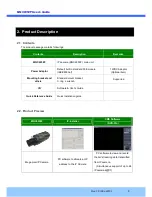
Page 9: ...module IEEE802 3af 12VDC Adaptor Optional item Mounting bracket and others Standard mount bracket C ring L wrench Supported CD Software User s Guide Quick Reference Guide Quick installation guide 2 2...

Page 10: ...GC C6 60 05 50 0F F U Us se er r s s G Gu ui id de e Rev 1 0 Dec 2013 10 2 3 Physical description 2 3 1 External View Figure 2 1 External view of MGC6050F 2 3 2 Rear panel Figure 2 2 Rear panel of MGC...

Page 11: ...It will be lit in green or red depending on the status Green Green color indicates that the camera is in normal operation mode Continuous green indicates that data transmission is possible Blinking gr...

Page 12: ...r and composite video output Pin assignments are as follows Pin Description Misc 1 RS 485 Plus For providing RS485 signal to RS485 devices 2 RS 485 Minus For providing RS485 signal to RS485 devices 3...

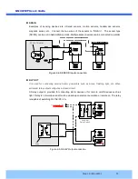
Page 13: ...ly Open CollectorType Photo Coupler Figure 2 4 SENSOR Input connection RLY OUT It is used for connecting external alarm generators such as sirens flashing light etc When activated relay output configu...

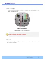
Page 14: ...to factory default state Press the switch for a few seconds while power is applied Figure 2 6 Factory Default switch of MGC6050F Restoring the factory default will erase all settings SD card slot Ple...

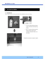
Page 15: ...ase follow through the following procedures for the installation on the wall or ceiling 1 Fix the mounting bracket and bracket holder on the wall or the ceiling using screws 2 Insert the bolt on the b...

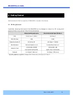
Page 16: ...running client programs Minimum requirement of the PC is described below Minimum Requirement Recommended Specification CPU Intel Core i3 3Ghz Intel Core i7 Main Memory 2GB 4GB Operating System Windows...

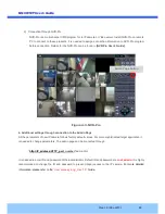
Page 17: ...ure 4 1 The DC power is applied through DC adaptor Figure 4 1 Power and network connection 2 Install IP installer and set IP parameters on MGC6050F Insert the CD provided with product into the PC Inst...

Page 18: ...ively If ADSL and Auto are selected the fields in is deactivated In case of ADSL fill the User Name and Password in with the values provided by your ISP If DDNS service is needed do the followings i C...

Page 19: ...d be installed on your PC before actual connection If your PC is not connected to the internet you cannot download Active X module Most convenient way of installing the Active X module is installing N...

Page 20: ...nal settings through connection to the Admin Page All the parameters of new IP camera follows factory default values For more sophisticated target application it is needed to change parameters The adm...

Page 21: ...roduct 2 The LAN switch supports standard PoE Make sure that both the IP camera and the LAN switch support standard PoE IEEE 802 3af In case of DC adaptor If PoE is not applied the power and network c...

Page 22: ...n Cmd Ping IP address Ex Ping 172 16 42 51 If Reply from message is returned in the figure below the network connection is in normal state Try connection to the video again If the problem persists or...

Page 23: ...r recording and still video capture in NVR pro and Web Viewer Windows Vista 1 UAC User Access Control configuration 1 Double click User Accounts in control panel 2 Double click Turn User Account Contr...

Page 24: ...F U Us se er r s s G Gu ui id de e Rev 1 0 Dec 2013 24 Windows 7 1 UAC User Access Control configuration 1 Double click User Accounts in control panel 2 Double click Change User Account Control settin...

Page 25: ...5 50 0F F U Us se er r s s G Gu ui id de e Rev 1 0 Dec 2013 25 2 Privilege Level Control 1 Select NVR icon on the desktop 2 Click right mouse button and select properties 3 Check Privilege Level in Co...

Page 26: ...013 26 5 4 Technical Assistance If you need any technical assistance please contact your dealer For immediate service please provide the following information 1 Model name 2 MAC address and Registrati...

Reviews: