background image

ENGLISH                                                                                                            


Rev1_23/03/21                                                                   Attached HERIONOVA_User_Manual_08/05/2019 


4.3 Installation 


The  lamp  fall-down  may  cause 
damage to persons and objects  


When mounting the lamp ensure 
that  the  original  fastenings  are 
used,  which  you  may  purchase 
from the supplier.


Make 

sure 

the 

mounting 

accessories 

have 

correctly 

installed 


Switch  off  the  power  supply  before 
proceeding to installation.  
 
Correct installation using only the 
original side-mounting brackets


H

NFX01


The 

Mounting 

Kit 

HNFX01 

is 

Composed of:


-


2  side  Brackets  1  left  and  1  right 
made of stainless steel. 

-


N.4 M6x10 screws with steel handle 
washers 


To  have  the  lamp  correctly  mounted 
without 

damaging 

the 

sealing 

gaskets,  the  lamp  has  to  be  fixed  to 
the  machine  structure  with  the 
HNFX01 

side-mounting 

brackets 

locked on the lamp. 


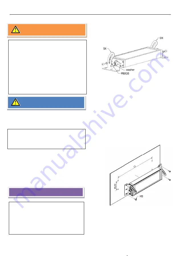
Hook  the  two  side  brackets  on 
the  lamp  sides  using  the  4  M6 
screws provided. (picture 12).


Bore  the  fixing  holes  on  the 
machine  surface,  as  shown  at 
par-  4.2,  page  8  (HNFX01  -  Side 
mounting pitch). 


After  the  fixing  holes  have  been 
made,  fix  the  lamp  to  the 
machine  structure  using  M5 
screws of at least 8 mm. length (2 
screws  for  each  fastener).  The 
plate  where  the  lamp  will  be 
mounted has to be at least 2 mm 
thick. 


The  lamp  position  can  be 
adjusted  by  rotating  the  same 
with  respect  to  the  standing 
surface  once  the  four M6 screws 
on each side have been loosened. 


ATTENTION


WARNING


Installation 

Loosen  to 

NOTICE


Picture 05 

Picture 04 

Summary of Contents for HERIONOVA Series

Page 1: ...1 ENGLISH HERIONOVA Series Installation Manual E506617 LOW VOLTAGE LUMINAIRE...

Page 2: ...nting accessories 8 4 3 Installation 9 5 Plug in 11 5 1 Low voltage plug in with M12 connector 11 5 2 Power cord 12 5 3 Integrated Power Cord 12 6 Switch on Switch off 13 7 Problem solving 13 8 Light...

Page 3: ...mechanical vibrations and processing shavings IP 67 degree of protection lamp Plug in to 24VDC Four lengths available Use only with class 2 power supply Suitable for wet location For cabinet use only...

Page 4: ...se Installation and use of the product is recommended only provided it is in perfect conditions and the user is well acquainted with all safety instructions CCEA the manufacturer waives any responsibi...

Page 5: ...ht source as it may cause a temporary reduction of vision Irritation aches damages or accidents may as well occur Avoid staring directly at the light source The device must be adjusted so as to avoid...

Page 6: ...ns for any issues Any product tampering or modifications not having been approved by the manufacturer will null and void the warranty 2 3 Damage risk levels Dangers where noncompliance may immediately...

Page 7: ...e the codes and see if you can identify the same model on the table hereunder The code printed on the brand name label shows the device s week and year of production Note Do not discard the product la...

Page 8: ...02 Rear Swivel Arm Mounting accessories 45 HNFX01 SIDE KIT BRACKET Model L1 in mm HN0221S02 HN0221S03 369mm 14 53in HN0321S02 HN0321S03 498mm 19 6in HN0521S02 HN0321S03 756mm 29 76in HN0721S02 HN0721S...

Page 9: ...To have the lamp correctly mounted without damaging the sealing gaskets the lamp has to be fixed to the machine structure with the HNFX01 side mounting brackets locked on the lamp Hook the two side b...

Page 10: ...ons of the fastening holes on the installation surface See the sizes table on page 8 HNFX01 for the drilling center lines Fasten the swivel mounting bracket to the lamp by tightening the screws at the...

Page 11: ...h M12 connector Wrong wiring may cause damages to the lamp All electrical connections have to be carried out by qualified electricians Please respect the polarity of connectors Always use the power co...

Page 12: ...RIPTION Cod M12TFC5 M12 A 4 poles 60VDC connector female with UL PVC Cable 3G1 5mmq Cross section Product code includes the above PIN Conductor 1 DC 24VDC black 1 2 Not connected 3 DC 0VDC black 2 4 N...

Page 13: ...cessary to replace the PCB LED if the lamp is properly installed and used following the instructions in this manual Please contact CCEA s Technical Support service or your Reseller in case the replace...

Page 14: ...ed out following different ways Any unauthorized repairs or attempts to repair the product Equipment operation under environmental conditions other than those specified in the user manual Liquid leaka...

Page 15: ...E Please refer to the data printed on the label or engraved on the lamp Power supply 22 36VDC Power input 26 5 40 66 5 93W see label IEC Class III Degree of protection IP67 Compatible WITH NEMA 6 LED...

Page 16: ...lass III device Degree of protection IP67 UL 2108 STANDARD FOR LOW VOLTAGE LIGHTING SYSTEM Edition 2 Revision Date 2017 05 30 CSA C22 2 NO 9 0 96 LUMINAIRES Edition 1 Revision Date 1998 07 01 Reaff 20...

Page 17: ...purpose luminaries CEI EN 62031 LED modules for general lighting Safety specifications CEI EN 62384 DC or AC supplied electronic control gear for LED modules Performance requirements This is a standa...

Reviews: