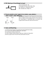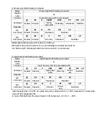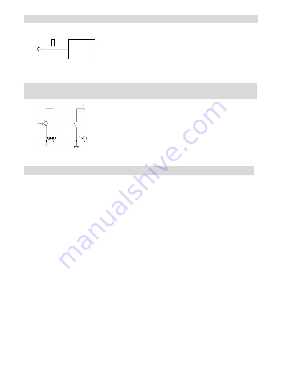
5. PDS Side Input Circuit (Negative logic)
Light intensity data: B1 – B8
Control signal: INT/EXT, WR, OFF/ON, TRIG
Use with driver IC or NPN open collector.
(Max. allowable input voltage: 6 V)
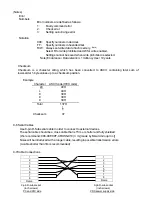
6. Recommended control signal drive circuits: open collector
photo-coupler, photo-MOS relay
When using the product in a noisy environment, we recommend
that you isolate the signal and ground lines from the control unit
with photo-couplers or photo-MOS relays. Any element that
supplies around 10mA can be used to drive the circuit.
7. Care and Handling
- Turn OFF the Power Supply and unplug from the wall socket before handing.
- Do not scratch the product by handling it with a hard object.
- Do not let water or cleanser enter the unit.
- Use soft cloth lightly soaked with water, mild soap, or alcohol, and wipe gently.
- Kerosene, organic solvent, and other chemicals should not be used.
LS05
LS06
etc
Switch
Relay
etc
Signal
Signal
4.7k
+5 V
Internal circuit


