34
Digital Recording Systems
Digital Recording Systems
2
3
4
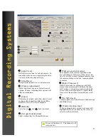
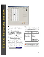
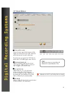
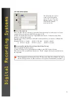
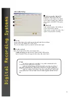
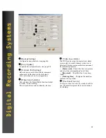
[Camera status bar]
Enables the camera status indicators on the main screen. The numbered buttons will flash when the cam-
eras detect motion.
2
[Sensor status bar]
Enables the Sensor status indicators on the main screen. The numbered buttons will flash when the sen-
sors are activated.
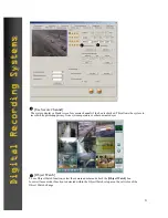
Place a check in the box next to each option to enable it on the main screen. The status bars will appear in
the area below the live cameras on the main view screen.
3
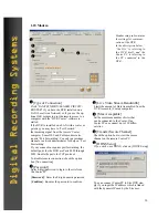
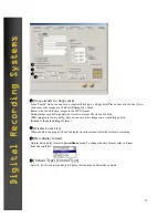
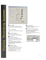
[Control status bar]
Enables the control relay status indicators on the main screen. The numbered buttons will flash when the
control relays are activated. You may also activate a control relay manually by clicking on its associated
button.
4
5
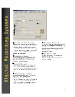
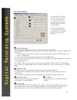
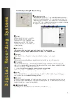
[Display motion detection grid]
If the motion detection grid is set to ‘Area Draw’ (Grid covers entire image) in the Motion Setup section,
a thin outline will appear around the outer edge of the live picture when motion is detected by a camera.
If you selected ‘Area Clear’ and used the custom masking options by “drawing” in several smaller motion
detection grids, then a thin outline will appear around the grid that is detecting motion within the picture.
You may select the color of the outlines (red or green)
in the Motion Setup section.
(The outlines will not appear in the recorded images.)
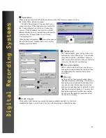
You can setup the Motion Detection to trigger a Control Output Device.
5


