V4 or RS485
Tx
-
Transmitter
1.
Connect the 3 ‘Video Input’ signals into the ‘Video In’ ports 1 to 3 (figure 1, 1-3).
2.
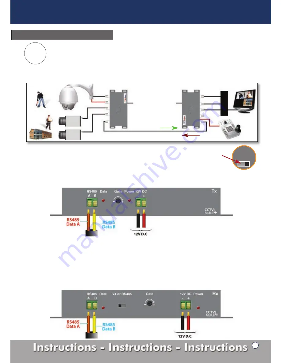
Move the switch from V4 to RS485 (figure 7a).
3.
The RG59 co-ax cable connects to the ‘Video Out’ (figure 1, 6), the maximum length for this cable is 200 metres.
4.
The RS485
Data A
cable of your RS485 device goes into the green ‘RS485’ socket (figure 8 below) marked
A
and the RS485
Data B
cable of your RS485 device goes into the socket marked
B
.
Tx
- Transmitter
Figure 8
Rx
-
Receiver
1.
Connect the RG59 co-ax cable into the ‘Video In’ port (figure 2, 5).
2.
Connect the 3 video cables from your DVR to the ‘Video Out’ marked 1 to 3 of the RX unit (figure 2, 1-3).
Note you should have no cables connected to the video port 4 on either the TX or RX.
3.
Connect your PTZ keyboard to the green ‘RS485’ socket (figure 9 below).
Data A
cable into the green ‘RS485’ socket
marked
A
and the RS485
Data B
cable of your device goes into the socket marked
B
.
4.
Move the switch from V4 to RS485 (figure 7a).
5.
The ‘Data’ LED will only light up when a keyboard/PTZ are in operation (figure 2, 7).
Rx
- Receiver
Figure 9
3 Video signals in one direction, 1 RS485 signal in the opposite direction .
Add extra cameras including a PTZ to an existing system using the RG59 cabling already installed. Perfect if you don’t
have access to run any more cables even data cables underground. The clever electronics of the Mule4 allow it to carry
the RS485 data along the same RG59 co-ax cable enabling the operator to monitor and control the system from a
different location. Figure 7 shows a diagram of how mode 2 is configured.
V1
Data
V2
V3
V1, V2, V3
in this direction
1x RG59 co-ax cable
D
V
R
RS485
Data
Mule 4 -
Tx
Mule 4 -
Rx
V1
Data
V2
V3
12V DC
12V DC
Figure 7
Operation Mode Setup
Mode
2
Switch in ‘RS485’
position
on both units.
Figure 7a
7
CCTV Mule Instructions


