background image

8

CD3000S 

3PH from 15A to 90A


User’s manual

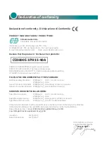
Declaration of conformity. . . . . . . . . . . . . . . . . . . . . . . . . . . . . . . . . .3

Important warnings for safety  .   .   .   .   .   .   .   .   .   .   .   .   .   .   .   .   .   .   .   .   .   .   .   .   .   .   .   .   .   .   .4

Maintenance  . . . . . . . . . . . . . . . . . . . . . . . . . . . . . . . . . . . . . . . . . .7

Quick Start  . . . . . . . . . . . . . . . . . . . . . . . . . . . . . . . . . . . . . . . . . . .9

1.1 Standard version  . . . . . . . . . . . . . . . . . . . . . . . . . . . . . . . . . . . . . . . . . . . 9

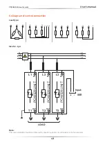
Basic Connections and sizing  . . . . . . . . . . . . . . . . . . . . . . . . . . . . . . 10

Identification and Order Code

  .   .   .   .   .   .   .   .   .   .   .   .   .   .   .   .   .   .   .   .   .   .   .   .   .   .   .   .   .   . 11

3.1 Identification of the Unit

  . . . . . . . . . . . . . . . . . . . . . . . . . . . . . . . . . . . . .  11

3.2 Order Code . . . . . . . . . . . . . . . . . . . . . . . . . . . . . . . . . . . . . . . . . . . . . . 12

Technical Specification

  . . . . . . . . . . . . . . . . . . . . . . . . . . . . . . . . . . 13

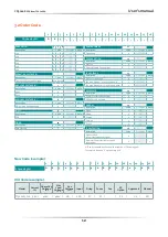
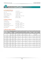
4.1 General features  . . . . . . . . . . . . . . . . . . . . . . . . . . . . . . . . . . . . . . . . . . 13
4.2 Input features  .   .   .   .   .   .   .   .   .   .   .   .   .   .   .   .   .   .   .   .   .   .   .   .   .   .   .   .   .   .   .   .   .   .   .   .   .   .   .   .   .   .   .   .   13
4.3 Power output features  . . . . . . . . . . . . . . . . . . . . . . . . . . . . . . . . . . . . . . 13
4.4 Environmental installation conditions  . . . . . . . . . . . . . . . . . . . . . . . . . . . . 14
4.5 Derating curve  . . . . . . . . . . . . . . . . . . . . . . . . . . . . . . . . . . . . . . . . . . . 14

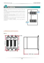
Installation  . . . . . . . . . . . . . . . . . . . . . . . . . . . . . . . . . . . . . . . . . . 15

5.1 Dimensions and fixing holes

. . . . . . . . . . . . . . . . . . . . . . . . . . . . . . . . . . . 15

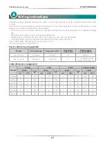
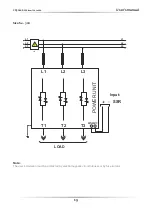
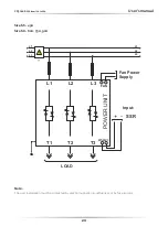
Wiring instructions   .   .   .   .   .   .   .   .   .   .   .   .   .   .   .   .   .   .   .   .   .   .   .   .   .   .   .   .   .   .   .   .   .   .   .   .   . 17

6.1 Diagram of control connection . . . . . . . . . . . . . . . . . . . . . . . . . . . . . . . . . 18

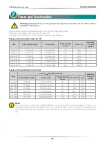
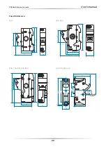
Fuses and Fuse holder  .   .   .   .   .   .   .   .   .   .   .   .   .   .   .   .   .   .   .   .   .   .   .   .   .   .   .   .   .   .   .   .   .   .   . 21

1

2
3

4

5

6

7

Summary

Summary of Contents for CD3000S 3PH

Page 1: ...AL Rev 04 2021 3PH From 15 to 90A 002 M 3000S3 15 90 CD3000S CD Automation S r l Via Picasso 34 36 20025 Legnano MI Italy Tel 39 0331 577479 Fax 39 0331 579479 E mail info cdautomation com Web www cdautomation com ...

Page 2: ......

Page 3: ...al safety Standard EN60947 1 2007 A1 2011 A2 2014 EN60947 4 3 2014 Generic Emission standard EN60947 4 3 2014 Group 1 Class A emissions Generic Immunity standard EN60947 4 3 2014 Industrial Immunity SODDISFA I REQUISITI DELLA NORMA Specifica di sicurezza EN60947 1 2007 A1 2011 A2 2014 EN60947 4 3 2014 Specifica sulle emissioni EN60947 4 3 2014 gruppo 1 emissioni classe A Specifica sulle Immunità E...

Page 4: ... Control Switches and equivalent to CSA C22 2 14 For more detail search for File E231578 on www ul com ESD Sensitive product use proper grounding and handling techniques when installing or servicing product Do not throw in trash use proper recycling techniques or consult manufacturer for proper disposal A NOTE marks a short message to alert you to an important detail A CAUTION safety alert appears...

Page 5: ...te for the environment and application AVERTISSEMENT L indice de protection du régulateur de puissance est de IP20 lorsque les couvercles sont installés et fermés L appareil doit être installé dans une enceinte qui assure toute la protection supplémentaire nécessaire pour l environnement et l application WARNING Ground the power controller via the provided protective earth grounding terminal Verif...

Page 6: ...AUTION The thyristor units here described have been designed for use with sinusoidal networks with nominal frequency 50 60 Hz Any application with NON SINUSOIDAL distorted or disturbed networks could compromise the correct operation of the unit ATTENTION Les unités de thyristors décrites ici ont été conçues pour être utilisées avec des réseaux sinusoïdaux d une fréquence nominale de 50 à 60 Hz Tou...

Page 7: ...horization RMA Customers wishing to return any items whether they are incorrectly supplied faulty or damaged in transit must first complete a Return Material Authorisation RMA form to obtain an RMA number from the Service Department A full repair service is available for customers Prior to submitting the RMA form and returning products customers are recommended to contact the technical support tea...

Page 8: ...ion and Order Code 11 3 1 Identification of the Unit 11 3 2 Order Code 12 Technical Specification 13 4 1 General features 13 4 2 Input features 13 4 3 Power output features 13 4 4 Environmental installation conditions 14 4 5 Derating curve 14 Installation 15 5 1 Dimensions and fixing holes 15 Wiring instructions 17 6 1 Diagram of control connection 18 Fuses and Fuse holder 21 1 2 3 4 5 6 7 Summary...

Page 9: ...tory and you just need to do the following steps 1 Verify CD3000S Sizing Be sure that The load current is equal or less than the Max current of CD3000S The load voltage is equal or less than the Max voltage of CD3000S 2 Verify the Order Code 3 Verify the Installation 4 Verify the Diagram of control connection verify that there isn t a short circuit on the load verify the Fan Power Supply only for ...

Page 10: ...al current of the load P Nominal power of the load Delta Wiring with resistive Load V Nominal load voltage phase to phase I Nominal current of the load P Nominal power of the load Open Delta Wiring with resistive Load V Nominal load voltage phase to phase I Nominal current of the load P Nominal power of the load 2 I P 1 73V I P 1 73V I P tot 3V V V V ...

Page 11: ... that the Thyristor unit have not damages If the product has a fault please contact the dealer from which you purchased the product The identification label give all the information regarding the factory settings of the Thyristor unit this label is on the unit like represented in figure Verify that the product is the same thing as ordered 3 ...

Page 12: ... code Note No Fan for unit 45A 0 Fan 110V Option for 45A to 90A units 1 110VFAN Fan 220V Standard for 45A to 90A units 2 not in the code APPROVALS 14 description Code OLD code Note CE EMC for European Market 0 CE EMC cUL us listed L UL MANUAL 15 description Code OLD code Note None 0 NM Italian 1 IM English 2 EM German 3 GM French 4 FM IP PROTECTION 16 description Code OLD code Note Standard IP20 a...

Page 13: ...tandard for size S4 S7 S8 ON 4Vdc OFF 1Vdc Logic input SSR 5 30Vdc 12mA Max low current ON 5Vdc OFF 1Vdc 4 3 Power output features Size Voltage range Repetitive peak reverse Voltage Latching current Max peak one cycle Leakage current I2 t value thyristor Frequency range Power loss Isolation Voltage A V 480V 600V mAeff 10ms A mAeff tp 10msec Hz I Inom W Vac 15A S2 24 480 1200 1200 150 230 15 610 47...

Page 14: ... dust corrosive gas vibration or water and also in salty environmental Altitude Up to 1000 meter over sea level For higher altitude reduce the nominal current of 2 for each 100m over 1000m Humidity From 5 to 95 without condense and ice Pollution Level Up to 2nd Level ref IEC 60947 1 6 1 3 2 4 5 Derating curve l max l nominal x K 1 15 20 25 30 35 40 45 50 55 1 2 1 0 8 0 6 0 4 0 2 0 1 1 1 1 0 9 0 8 ...

Page 15: ...ordered The Thyristor unit must be always mounted in vertical position to improve air cooling on heat sink Maintain the minimum distances in vertical and in horizontal as represented When more unit has mounted inside the cabinet maintain the air circulation like represented in figure Sometimes is necessary installing a fan to have better air circulation 5 5 cm 15 cm 2 cm AIR AIR 5 1 Dimensions and...

Page 16: ...16 CD3000S 3PH from 15A to 90A User s manual Ø 4 5 mm 117 mm 65 mm 138 mm 110 mm Size S4 Size S6 Ø 4 5 mm 117 mm 120 mm 65 mm 110 mm 123 mm 123 mm Size S8 159 mm Ø 4 5 mm 117 mm 65 mm 138 mm 110 mm ...

Page 17: ...cal regulations regarding electrical installation should be rigidly observed Use copper cables and wires rated for use at 75 C only Use wire terminal UL Listed ZMVV Power cable torque suggested Current Connector Type Torque Lb in N m Wire Range AWG kcmil Wire Terminal UL listed ZMVV 15A 30A 45A M5 Screw 26 6 3 0 8 Wire Pin 60A 75A 90A M6 Screw 70 8 8 0 1 Fork Spade terminal Copper Tube Crimp Lug C...

Page 18: ...tion Load type Note The user installation must be protected by electromagnetic circuit breaker or by fuse isolator L2 L1 L2 L3 L3 L1 SSR T2 A2 L2 A1 POWER UNIT T1 A2 L1 A1 POWER UNIT T3 A2 L3 A1 POWER UNIT LOAD Input T1 T2 T3 T1 T2 T3 T1 T2 T3 N T1 L1 L3 L2 T2 T3 Size S2 15A ...

Page 19: ... from 15A to 90A User s manual 19 Size S4 30A Note The user installation must be protected by electromagnetic circuit breaker or by fuse isolator L2 L1 L2 L3 L3 L1 SSR T1 L2 T3 T2 A1 A2 L3 L1 POWER UNIT LOAD Input ...

Page 20: ...ser s manual Size S6 45A Size S8 60A 75A 90A Note The user installation must be protected by electromagnetic circuit breaker or by fuse isolator L2 L1 L2 L3 L3 L1 SSR T1 L2 FAN T3 T2 A1 A2 L3 L1 POWER UNIT LOAD Input Fan Power Supply ...

Page 21: ...58 FU2258 80A 80 6550 1 75A S8 FFH2258 FU2258 100A 100 13500 1 90A S8 FFH2258 FU2258 125A 125 14000 1 Fuses and Fuse Holder Code for UL Size 200 kARMS Symmetrical A I C Quantity for each phase Fuse Holder Code Fuse Code Total Current ARMS I2 t A2 sec Vac 15A S2 FFH1038 FU1038 16AUL 16 150 600 1 30A S4 FFH1451 FU1451 40AUL 40 750 700 1 45A S6 FFH1451 FU1451 50AUL 50 1800 700 1 60A S8 FFH2258 FU2258...

Page 22: ...000S 3PH from 15A to 90A User s manual 86 81 37 58 17 8 45 95 5 49 42 5 69 27 45 117 5 112 43 70 36 45 0 5 146 75 35 25 5 118 40 3 117 87 8 57 6 5 Fuse Holder size 15A 60A 75A CE 90A CE 75A UL 90A UL 30A 45A ...

Page 23: ...CD Automation S r l Via Picasso 34 36 20025 Legnano MI Italy Tel 39 0331 577479 Fax 39 0331 579479 E mail info cdautomation com Web www cdautomation com ...

Reviews: