background image

46

REVO PC


User’s manual

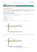
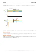
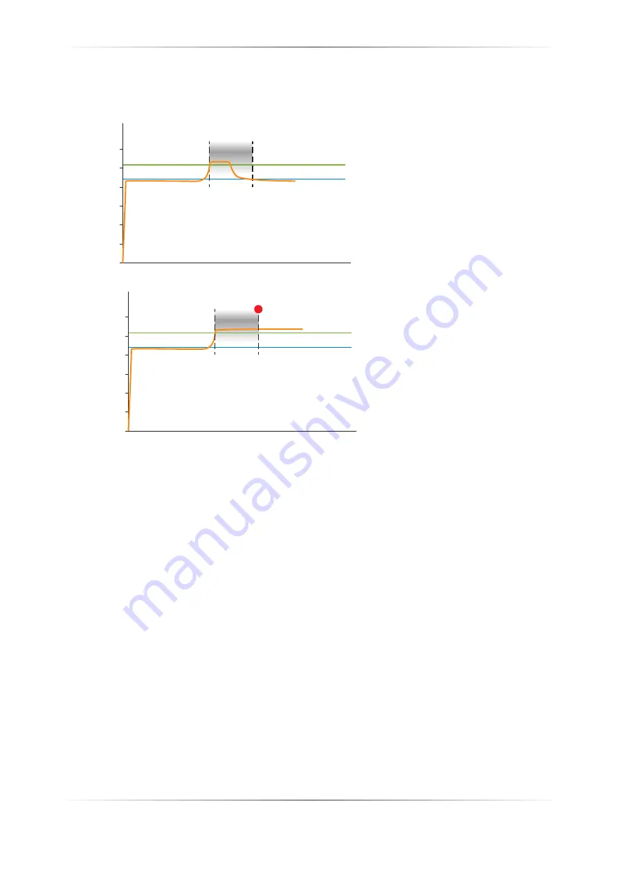
Using the HB Delay parameter, the alarm intervention can be delayed (menu System, see paragraph 7.2.2).

HB delay (es: 2.5 sec.)

NO ALARM

22: R  (V/I)

HB sense (+20%)

26,4

30

25

20

15

10

5

0

Ohm

HB delay (es: 2.5 sec.)

ALARM

22: R  (V/I)

HB sense (+20%)

26,4

30

25

20

15

10

5

0

Ohm

Sensitivity (HB sense) and delay (HB delay) can be varied according to the application (menu System, see 
paragraph 7.2.2).

8.2 Short Circuit

This alarm is activated if the unit detects a short circuit in one of the power devices. This alarm could also 
activate when the current measured by the unit is greater than 80% of the value set in Nominal I.

8.3 Thermal alarm

When the heatsink temperature reaches the temperature set in the “Temperature Alarm Setpoint” value the 
power output are forced to 0% (see paragraph 7.2.6).

Summary of Contents for REVO PC M-RPC

Page 1: ...USER S MANUAL Rev 10 2021 007 M RPC CD Automation S r l Via Picasso 34 36 20025 Legnano MI Italy Tel 39 0331 577479 Fax 39 0331 579479 E mail info cdautomation com Web www cdautomation com ...

Page 2: ......

Page 3: ...ety Standard EN60947 1 2007 A1 2011 A2 2014 EN60947 4 3 2014 Generic Emission standard EN60947 4 3 2014 Group 1 Class A emissions Generic Immunity standard EN60947 4 3 2014 Industrial Immunity SODDISFA I REQUISITI DELLA NORMA Specifica di sicurezza EN60947 1 2007 A1 2011 A2 2014 EN60947 4 3 2014 Specifica sulle emissioni EN60947 4 3 2014 gruppo 1 emissioni classe A Specifica sulle Immunità EN60947...

Page 4: ...witches and equivalent to CSA C22 2 14 For more detail search for File E231578 on www ul com ESD Sensitive product use proper grounding and handling techniques when installing or servicing product Do not throw in trash use proper recycling techniques or consult manufacturer for proper disposal A NOTE marks a short message to alert you to an important detail A CAUTION safety alert appears with info...

Page 5: ... environment and application AVERTISSEMENT L indice de protection du régulateur de puissance est de IP20 lorsque les couvercles sont installés et fermés L appareil doit être installé dans une enceinte qui assure toute la protection supplémentaire nécessaire pour l environnement et l application WARNING Ground the power controller via the provided protective earth grounding terminal Verify ground i...

Page 6: ... thyristor units here described have been designed for use with sinusoidal networks with nominal frequency 50 60 Hz Any application with NON SINUSOIDAL distorted or disturbed networks could compromise the correct operation of the unit ATTENTION Les unités de thyristors décrites ici ont été conçues pour être utilisées avec des réseaux sinusoïdaux d une fréquence nominale de 50 à 60 Hz Toute applica...

Page 7: ... RMA Customers wishing to return any items whether they are incorrectly supplied faulty or damaged in transit must first complete a Return Material Authorisation RMA form to obtain an RMA number from the Service Department A full repair service is available for customers Prior to submitting the RMA form and returning products customers are recommended to contact the technical support team to deter...

Page 8: ...ecifications 19 3 1 General features 19 3 2 Input features 19 3 3 Output features power device 19 3 4 Environmental installation conditions 19 Installation 20 4 1 Dimensions and Weight 20 4 2 Fixing holes 20 4 3 External Current Sensor dimensions 20 Wiring instruction 21 5 1 Command terminals 22 5 2 Master Revo PC Connection Diagram 23 5 3 Thyristor unit interface 24 5 4 Digital 0utput 25 5 5 Anal...

Page 9: ...5 11 Revo PC3 details 34 Control Panel 35 6 1 Display 36 6 2 Displayed parameters 37 Configurator software 38 7 1 Configuration cable 38 7 2 Test View main page 39 Alarm description 45 8 1 Heater Break Alarm 45 8 2 Short Circuit 46 8 3 Thermal alarm 46 Communication 47 6 7 8 9 ...

Page 10: ...r maintained close to 1 Stay connected with the most popular Field Bus protocols Eliminate use of PLC output modules by using comms for Power to CPU connections Alarm notification per zone of heater break and thyristor short circuit Product footprint for 24 zone package 50 less than using standard thyristor stacks Dramatic savings with less wiring smaller cabinet enclosures REVO PC s considered de...

Page 11: ...ch channel is reduced proportionally to restrict power overshoot This function significantly reduces disturbances on the main network compared to a full power system preventing any increase in energy tariffs imposed by the electricity supplier This function can be activated deactivated and the limit value changed at any time 1 1 2 3 4 5 00V 0 0s Auto 37 0 3 2 M A 500 M V 200 0 M S 1 1 18V Acquisit...

Page 12: ...t and medium waveform Input SSR Standard Operating temperature 0 to 40 without derating Comply with EMC and cUL up to 700A UL for 800A as an option 100KA Short Circuit rating SSCR up to 600V Data Sheet More details on REVO S 1PH Manual Control Unit REVO PC up to 24 channels SSR outputs to control up to n 24 REVO S 1PH High precision current transducer High precision voltage transducer RS485 and Mo...

Page 13: ...1 12 13 14 15 16 R S 1 1 2 0 4 0 S Z 0 F 0 0 2 1 R S 1 1 2 0 4 0 S Z 0 F 0 0 2 1 REVO PC2 Example Control Unit REVO PC3 to control 8 load three phase with control on 3 phase 3PH with 8 channel Current transformer input to detect all the current This unit transform a simple SCR Power Switch into an Intelligent Unit able to communicate and to detect load failure or short circuit on SCR Power Unit N ...

Page 14: ...the Thyristor unit have not damages If the product has a fault please contact the dealer from which you purchased the product The identification s label give all the information regarding the factory settings of the unit this label is on the unit like represented in figure Verify that the product is the same thing as ordered 2 ...

Page 15: ...t Sensor Input for each channel 7 8 9 description code Current Sensor is included and integrated with REVO S 1PH units with Y Option 0 0 0 Communication 10 description code N 1 Ethernet Port Modbus TCP and N 3 Modbus RTU 1 N 1 Profibus DP Port 4 N 1 Ethernet Port ProfiNet 5 Aux Voltage to be coupled with an external transformer 11 description code 24Vdc 4 Firing 12 description code Half Cycle at 5...

Page 16: ...th REVO S 1PH units with Y Option 0 0 0 Communication 10 description code N 1 Ethernet Port Modbus TCP and N 3 Modbus RTU 1 N 1 Profibus DP Port 4 N 1 Ethernet Port ProfiNet 5 Aux Voltage to be coupled with an external transformer 11 description code 24Vdc 4 Firing 12 description code Half Cycle at 50 power demand 1 One Cycle at 50 power demand 2 FEED BACK Control Mode 13 description code No Feed ...

Page 17: ...s with Y option are required COMMUNICATION 10 description code N 1 Ethernet Port Modbus TCP and N 3 Modbus RTU 1 N 1 Profibus DP Port 4 N 1 Ethernet Port ProfiNet 5 Aux Voltage to be coupled with an external transformer 11 description code 24Vdc 4 FIRING 12 description code One Cycle at 50 power demand 2 FEED BACK Control Mode 13 description code No Feed Back 1 Power 2 APPROVALS 14 description cod...

Page 18: ...re required 0 0 0 Current Sensor is included and integrated with REVO S 1PH units with Y Option COMMUNICATION 10 description code N 1 Ethernet Port Modbus TCP and N 3 Modbus RTU 1 N 1 Profibus DP Port 4 N 1 Ethernet Port ProfiNet 5 Aux Voltage to be coupled with an external transformer 11 description code 24Vdc 4 FIRING 12 description code One Cycle at 50 power demand 2 FEED BACK Control Mode 13 d...

Page 19: ...V 3 3 Output features power device Open collettor max 50mA 3 4 Environmental installation conditions Ambient temperature 0 40 C 32 104 F at nominal current max 50 C Storage temperature 25 C a 70 C 13 F to 158 F Installation place Don t install at direct sun light where there are conductive dust corrosive gas vibration or water and also in salty environmental Altitude Up to 1000 meter over sea leve...

Page 20: ... mm 95 H mm 269 Weight Kg 0 6 5 5 71 239 5 5 4 2 Fixing holes 4 3 External Current Sensor dimensions 50 0 05A 9 mm 37 mm 6 mm 18 mm 18 mm 14 mm 40 mm 37 mm 19 mm 19 mm 40 mm 9 mm 49 mm 6 mm 27 mm 27 mm 18 mm 51 mm 49 mm 29 mm 29 mm 51 mm 100 0 05A 250 0 05A from 400 0 05A please ask ...

Page 21: ...practices rules is opportune take some precautions The coil contactor the relays and other inductive loads must be equipped with opportune RC filter Use shielded bipolar cables for all the input and output signals The signal cables must not be near and parallel to the power cables Local regulations regarding electrical installation should be rigidly observed 5 M1 Sync L1 R L2 S L3 T N MC1 MC2 ...

Page 22: ...U Slave 2 11 RS485 B 12 Not connected 13 GND 0V 14 C Common contact alarm relay output 15 NC Normally Close contact alarm relay output 16 NO Normally Open contact alarm relay output Terminal Block MC2 Terminal MC2 Description 1 24Vdc OUT 2 GND 0V 3 12Vdc OUT 12V 30mA max 4 RS485 A Modbus RTU Slave 3 5 RS 485 B Terminal Block M1 Terminal M1 Description 1 L1 R 2 Not connected 3 L2 S 4 Not connected ...

Page 23: ... B L1 R Fuse 0 5A L2 S L3 T Wire section 1mm2 N B A A RS485 Mod Bus 3 B A C GND 0V NC NO RELAYALARM OUTPUT Di1 Di2 Di3 Di4 0Vdc 24Vdc 24Vdc 12Vdc OUT 12V 30mA max OUT GND 0V 1 2 3 4 5 COMMON Digital Input AUX Modbus TCP L MC1 M1 MC2 5 2 Master Revo PC Connection Diagram Caution this procedure must be performed only by qualified persons ...

Page 24: ... 3 6 4 ISO7 TLP187 1 3 6 4 ISO8 TLP187 M5 12 R22 270R 1 R35 4K7 1 R23 270R 1 R36 4K7 1 R24 270R 1 R37 4K7 1 R25 270R 1 R38 4K7 1 R26 270R 1 R39 4K7 1 R27 270R 1 R40 4K7 1 R28 270R 1 R41 4K7 1 R29 270R 1 R42 4K7 1 OUT1 KPTR 3216CGCK R8 270R 1 OUT2 KPTR 3216CGCK R9 270R 1 OUT3 KPTR 3216CGCK R10 270R 1 OUT4 KPTR 3216CGCK R11 270R 1 OUT5 KPTR 3216CGCK R12 270R 1 OUT6 KPTR 3216CGCK R13 270R 1 OUT7 KPTR...

Page 25: ...tal Output 11 7 Digital Output 12 8 Digital Output 13 9 Digital Output 14 10 Digital Output 15 11 Digital Output 16 12 Not connected Terminal M7 Description Phase 3 1 GND 2 24Vdc 3 Com Digital Output 4 Digital Output 17 5 Digital Output 18 6 Digital Output 19 7 Digital Output 20 8 Digital Output 21 9 Digital Output 22 10 Digital Output 23 11 Digital Output 24 12 Not connected See the diagram on th...

Page 26: ...al Out 7 15 23 Digital Out 6 14 22 Digital Out 5 13 21 Digital Out 4 12 20 Digital Out 3 11 19 Digital Out 2 10 18 Digital Out 1 9 17 Com Dig Out 24Vdc CH8 CT8 CT7 CT6 CT5 CT4 CT3 CT2 CT1 CT8 CT7 CT6 CT5 CT4 CT3 CT2 CT1 1 8 CH7 CH6 CH5 CH4 CH3 CH2 CH1 COM 24 GND GND LOAD LOAD LOAD LOAD LOAD LOAD LOAD LOAD L1 L2 N L1 L2 N 3 4 1 2 5 6 CT 1 2 3 4 5 6 H B S C ON CAL T1 L1 CT 1 2 3 4 5 6 H B S C ON CAL...

Page 27: ...REVO PC User s manual 27 Recommended cable 035 mm2 AWG 22 Recommended cable 1 mm2 If the cable is too thick cut the plastic part with a cutter ...

Page 28: ...5 Current transformer input Channel 5 CT13 Current transformer input Channel 13 CT6 Current transformer input Channel 6 CT14 Current transformer input Channel 14 CT7 Current transformer input Channel 7 CT15 Current transformer input Channel 15 CT8 Current transformer input Channel 8 CT16 Current transformer input Channel 16 Terminal M4 Description CT17 Current transformer input Channel 17 CT18 Cur...

Page 29: ... 2 on phase L2 Ch18 Channel 2 on phase L3 Ch3 Channel 3 on phase L1 Ch11 Channel 3 on phase L2 Ch19 Channel 3 on phase L3 Ch4 Channel 4 on phase L1 Ch12 Channel 4 on phase L2 Ch20 Channel 4 on phase L3 Ch4 to SSR input TH4 Ch12 to SSR input TH12 Ch20 to SSR input TH20 TH1 TH9 TH17 TH4 TH20 TH12 CT4 on M2 CT20 on M4 CT12 on M3 CT17 on M4 CT9 on M3 CT1 on M2 Ch1 to SSR input TH1 Ch9 to SSR input TH9...

Page 30: ... 4 on phase L2 Ch20 Channel 4 on phase L3 Ch5 Channel 5 on phase L1 Ch13 Channel 5 on phase L2 Ch21 Channel 5 on phase L3 Ch6 Channel 6 on phase L1 Ch14 Channel 6 on phase L2 Ch22 Channel 6 on phase L3 Ch7 Channel 7 on phase L1 Ch15 Channel 7 on phase L2 Ch23 Channel 7 on phase L3 Ch8 Channel 8 on phase L1 Ch16 Channel 8 on phase L2 Ch24 Channel 8 on phase L3 Ch8 to SSR input TH8 Ch16 to SSR input...

Page 31: ... 2 on phase L2 Ch18 Channel 2 on phase L3 Ch3 Channel 3 on phase L1 Ch11 Channel 3 on phase L2 Ch19 Channel 3 on phase L3 Ch4 Channel 4 on phase L1 Ch12 Channel 4 on phase L2 Ch20 Channel 4 on phase L3 CT1 on M2 CT4 on M2 CT17 on M4 CT9 on M3 TH1 TH4 TH17 TH9 CT20 on M4 TH20 CT12 on M3 TH12 L1 L2 L3 N L1 L2 L3 N Ch4 to SSR input TH4 Ch12 to SSR input TH12 Ch20 to SSR input TH20 Ch1 to SSR input TH...

Page 32: ... 4 on phase L2 Ch20 Channel 4 on phase L3 Ch5 Channel 5 on phase L1 Ch13 Channel 5 on phase L2 Ch21 Channel 5 on phase L3 Ch6 Channel 6 on phase L1 Ch14 Channel 6 on phase L2 Ch22 Channel 6 on phase L3 Ch7 Channel 7 on phase L1 Ch15 Channel 7 on phase L2 Ch23 Channel 7 on phase L3 Ch8 Channel 8 on phase L1 Ch16 Channel 8 on phase L2 Ch24 Channel 8 on phase L3 CT1 on M2 CT8 on M2 CT17 on M4 CT9 on ...

Page 33: ...details On REVO PC2 is possible to control 8 LOAD Three phase with control on two phase 2PH with 8 Channel Ch1 Channel 1 on phase L1 Ch17 Channel 1 on phase L3 Ch2 Channel 2 on phase L1 Ch18 Channel 2 on phase L3 Ch3 Channel 3 on phase L1 Ch19 Channel 3 on phase L3 Ch4 Channel 4 on phase L1 Ch20 Channel 4 on phase L3 Ch5 Channel 5 on phase L1 Ch21 Channel 5 on phase L3 Ch6 Channel 6 on phase L1 Ch...

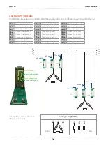
Page 34: ...h19 Channel 3 on phase L3 Ch4 Channel 4 on phase L1 Ch12 Channel 4 on phase L2 Ch20 Channel 4 on phase L3 Ch5 Channel 5 on phase L1 Ch13 Channel 5 on phase L2 Ch21 Channel 5 on phase L3 Ch6 Channel 6 on phase L1 Ch14 Channel 6 on phase L2 Ch22 Channel 6 on phase L3 Ch7 Channel 7 on phase L1 Ch15 Channel 7 on phase L2 Ch23 Channel 7 on phase L3 Ch8 Channel 8 on phase L1 Ch16 Channel 8 on phase L2 C...

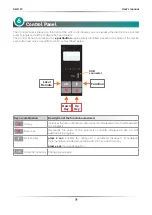
Page 35: ...ction as described below Key or combination Description of the function associated UP key Increases thevalue ofthe parametercurrentlydisplayedwhen an edit operation is in progress Down key Decreases the value of the parameter currently displayed when an edit operation is in progress Function key press 2 sec Enables the change of a parameter displayed if available incrementable and decrementabile w...

Page 36: ...enable command Fixed enable command Flashing ratio show the number of connected slave i e 3 blink 3 slave Flashing global communication traffic when active Heasink over temperature Flashing Thermal alarm Fixed Heater Break or Short Circuit or Current Limit or Comm WatchDog alarm All ON ...

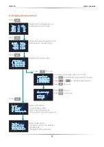
Page 37: ...255 255 000 G 192 168 100 101 Press Press Press Press for 2 sec Press Shows status voltage line and total power for each stage Shows heat sink temperature and line frequency for each stage Modbus TCP configuration System information Logic power supply Main board temperarture Time system from first power on System information Firmware Version and Release Model code Modbus TCP Mac address An undersc...

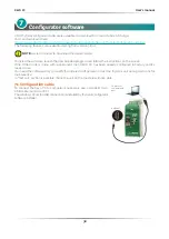
Page 38: ...ogram and follow the instructions on the screen If the Order Code is in line with requirement then REVO PC has been already configured in Factory and it s ready to use You need the software only to modify the ordered configuration or test the thyristor unit during startup or for maintenance In Test unit section is possible check the unit on the machine with live data 7 1 Configuration cable To con...

Page 39: ...wer Set Point Configure and Monitor the Digital Inputs Detect if an alarm is activated Set voltage and power of each load Main process variable display Source power set point display Total power limit setting Power setting Power output percentage Product informations Communication write allowed Power limit Zone enable Load setting Digital Input status Digital Output status Stages variable informat...

Page 40: ...ed by the specific channel Load V set the nominal voltage of the heating element drived by the specific channel Channel 1 8 kW Channel 2 10 kW Channel 3 10 kW Channel 4 8 kW Channels 5 6 7 8 Not available on REVO PC Channel 9 8 kW Channel 10 10 kW Channel 11 10 kW Channel 12 8 kW Channels 13 14 15 16 Not available on REVO PC Channel 17 8 kW Channel 18 10 kW Channel 19 10 kW Channel 20 8 kW Channel...

Page 41: ... kW Channel 5 10 kW Channel 6 10 kW Channel 7 8 kW Channel 8 Not used but available Channel 9 8 kW Channel 10 10 kW Channel 11 10 kW Channel 12 8 kW Channel 13 10 kW Channel 14 10 kW Channel 15 8 kW Channel 16 Not used but available Channel 17 8 kW Channel 18 10 kW Channel 19 10 kW Channel 20 8 kW Channel 21 10 kW Channel 22 10 kW Channel 23 8 kW Channel 24 Not used but available L1 L2 L2 L3 L3 L1...

Page 42: ...fig and Communication values 2 2222 Like Level 1 can set System values 7 2 3 Monitor tab menu Show some read only value useful for installation and control On Main Board Aux Power Supply power supply connected on terminal 1 and 2 of M1 connector or terminal 1 and 2 of M2 connector Logic Power Supply Internal power supply Main board Temp Temperature of main board On each Stages Temp stg Temperature...

Page 43: ...be used to connect an external master like a PLC or a HMI Watch dog Set the amount of time to wait for a communication message before triggering the watchdog error To disable set it to 0 On each Com Ports The communications ports are every time enabled but is possible allow write a parameter Write Enable Allow to write a parameter WD Enable the WatchDog function WD Led Light on if WatchDog is acti...

Page 44: ...e incoming line supply V2 Square Voltage feed back The input signal is proportional to the output square voltage This means that input signal becomes a power demand The power remains constant if the load impedance doesn t change P VxI Power feed back The input signal is proportional to the power output This means that input signal becomes a power demand The power remains constant also if voltage a...

Page 45: ...nal Resistance R Load V Nominal I The alarm threshold value is the value of the nominal resistance increased by the percentage defined by the HB Sense parameter menu System see paragraph 7 2 2 Example Resistance 2200W 220V power voltage A 2200 220 10A Load V 220 V nominal I 10A Nominal resistance R 22 Ohm HB sense parameter 20 threshold value 22 22 x 20 100 22 4 4 Ohm 26 4 Ohm 22 R V I HB sense 20...

Page 46: ... sense and delay HB delay can be varied according to the application menu System see paragraph 7 2 2 8 2 Short Circuit This alarm is activated if the unit detects a short circuit in one of the power devices This alarm could also activate when the current measured by the unit is greater than 80 of the value set in Nominal I 8 3 Thermal alarm When the heatsink temperature reaches the temperature set...

Page 47: ...C User s manual 47 Communication Modbus TCP communication port is available as standard Other serial communication port are available as option 9 Standard Modbus TCP Option Ethernet IP Profinet Option Profibus ...

Page 48: ...CD Automation S r l Via Picasso 34 36 20025 Legnano MI Italy Tel 39 0331 577479 Fax 39 0331 579479 E mail info cdautomation com Web www cdautomation com ...

Reviews: