32
REVO S
3PH from 300A to 800A
User’s manual
Supply the electronic board
The REVO S thyristor unit, to work, requires a voltage supply for the electronic boards. The Max consumption is
10VA. The voltage supply for the electronic boards is configured in line with customer requirements that are
defined in the Order Code. The Order Code is written on the identification label.
Warning:
Before connecting or disconnecting the unit check that power and control cables
are isolated from voltage sources.
Specialised personnel only
Terminal M1
Description
18
Voltage Supply for Electronic Boards (Auxiliary Voltage)
19
Not Used
20
Voltage Supply for Electronic Boards (Auxiliary Voltage)
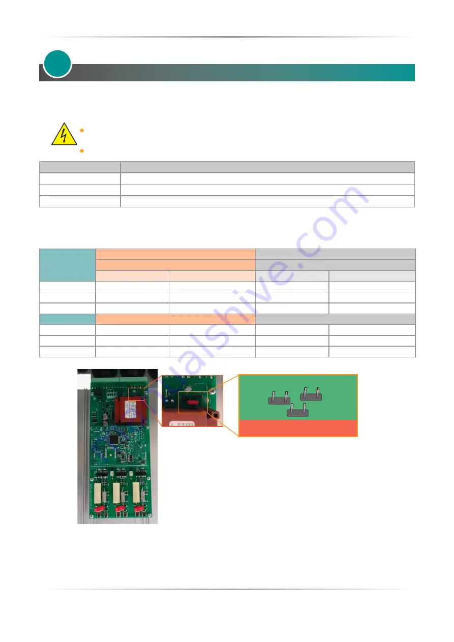
If it is necessary to change the value of the auxiliary supply voltage, move the jumpers as shown in the table
below.
The range of the auxiliary voltage that can be set depends on the transformer mounted on the board, see the
ordering code on Digit 8 (see table).
Order Code
As ordered
Change to
Jumper JP1 + JP2 are linked
Link only Jumper JP3
Transformer range
Line voltage
Transformer range
Line voltage
RS3_ _ _-_
1
90:135V
100/120V
180:265V
200/208/220/230/240V
RS3_ _ _-_
2
180:265V
200/208/220/230/240V
342:528V
380/400/415/440/480V
RS3_ _ _-_
3
238:330V
277V
540:759V
600/690V
Only Jumper JP3 is linked
Link Jumper JP1 + JP2
RS3_ _ _-_
5
342:528V
380/400/415/440/480V
180:265V
200/208/220/230/240V
RS3_ _ _-_
6
540:759V
600V
238:330V
277V
RS3_ _ _-_
7
540:759V
690V
238:330V
277V
11
•
Attention! never link all the jumpers JP1+JP2+JP3 at the same time or JP3 + any other jumper, JP3 must
be always alone, follow only the configuration shown.
•
Attention! The auxiliary voltage is also used for firing synchronism, so it must be in phase with the
load voltage.
JP1
JP2
JP3


