


12
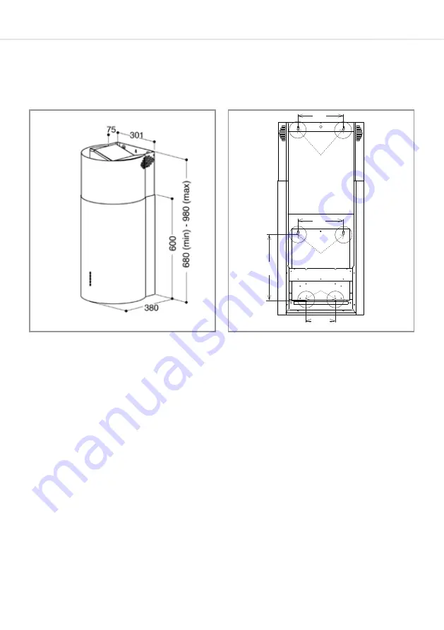
There are images below showing the extractor dimensions (Fig. 3)
and mounting hole positions (Fig. 4). These are intended to help with
preparation for installing the extractor.
Fig. 3
Taking into account the extractor dimensions, and the advice
regarding installation height as per page 11, roughly mark the screw
hole positions ‘A’ and ‘B’ (shown in Fig. 4) for the extractor.
We advise you seek the aid of the person(s) helping you to support
the body of the extractor whilst you mark out the holes marked as ‘A’
in Fig. 4.
Ensure that you are happy with where the extractor will be and the
height it will sit at above the hob or surface below.
C
A
B
128.5
200
200
310
Fig. 4


