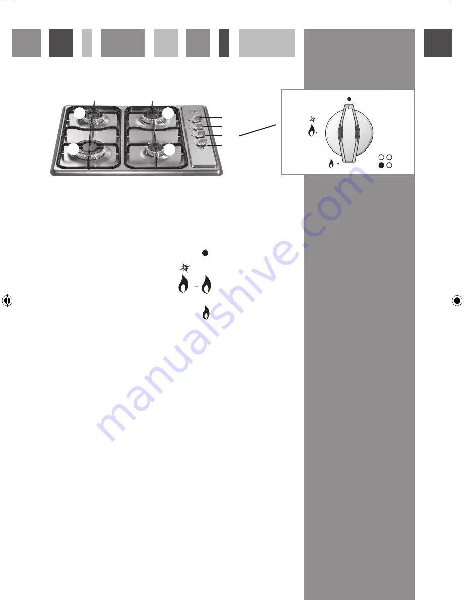
Using your hob
Fig.1
2
3
1
4
5
6
7
8
Gas burners:
1. Rapid burner
3.0kW
2. Left Semi-Rapid burner 1.75kW
3. Right Semi-Rapid burner 1.75kW
4. Auxiliary burner
1.0kW
Control panel:
5. Right Semi-Rapid burner control knob
6. Left Semi-Rapid burner control knob
7. Rapid burner control knob
8. Auxiliary burner control knob
This appliance is class 3
Gas burners:
Gas flow to the burners is controlled by the control knobs (5, 6, 7
and 8 on the diagram above). There are 3 positions shown on the
control panel. Turning the control knob to the positions shown
below achieves the following:
Closed (OFF position)
Maximum position: Provides fast boiling function
Minimum position: Provides simmer function
The flame can be set to the desired position by turning
the control knob through the adjustment range in an anti-
clockwise direction.
0220 HCG500 HCG520 Manual.indd 3
26/6/09 09:35:49
Summary of Contents for HCG501
Page 11: ...Notes...


