background image

30

  If a splashback/worktop upstand  
  is to be fitted, take this into account  
  when cutting the hole.  The minimum  
  distance that the hob should be   
  positioned away from the rear wall  
  or splashback is 50mm.

2.   Make sure that the worktop is clean 

and dust free and insert the hob 
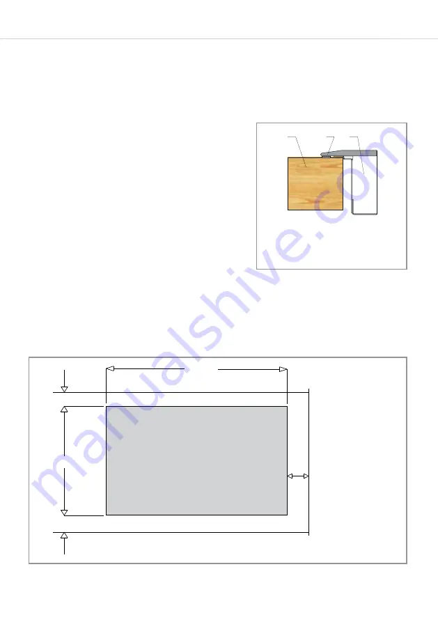
into the cut-out opening. Press the 
hob firmly into place so that the seal 
connects with the worktop (Fig. 7).

Fig.8

1 - Worktop

3 - Induction hob

3

2

1

2 - Hob seal

Fig.7

Rear Wall

Front edge of worktop

Adjacent vertical surface 

(cupboard etc. - 

Measurement applicable 

to both sides.)

870

500

Min.

Cut-out

61

Min. 60

Min.

55

Summary of Contents for HN9850FR

Page 1: ...www cda eu HN9850FR Induction Hob Installation use and maintenance...

Page 2: ...your hob 11 Booster function 12 Operating time limiter 13 Timer minute minder 14 Setting the timer on multiple zones 16 Pause function 17 Keep warm function 17 Bridge function 19 Safety key lock 20 Re...

Page 3: ...uirements and extractor heights 29 How to install the hob including hob cut out dimensions 30 Hob cut out dimensions 31 Mains electricity connection 32 Terminal block connections and rated power 33 En...

Page 4: ...supervision or instructions on how to use the appliance by someone who is responsible for their safety Under no circumstances should any external covers be removed for servicing or maintenance except...

Page 5: ...d resources As a reminder of the need to dispose of household appliances separately the product is marked with a crossed out wheeled dustbin Please note Induction hobs become hot and remain hot during...

Page 6: ...een designed for use only as a cooking appliance Any other use should be considered incorrect and therefore dangerous FOR THOSE WITH HEART PACEMAKERS OR ACTIVE IMPLANTS The function of this hob confor...

Page 7: ...vity or cause unwanted activation Do not lean over pans when they are warming up or cooking Saving energy Using energy in a responsible way not only saves money but also helps the environment The foll...

Page 8: ...be better distributed meaning cooking is more even Most cookware is compatible with induction cooking There are three ways to check the suitability of your cookware 1 Using a magnet to see if the bas...

Page 9: ...tor 8 Pause function sensor with LED 2 Cooking zone indicator 9 On off sensor 3 Timer activity indicator 10 Safety key lock sensor with LED 4 Bridge function indicator 11 Booster function sensor 5 Tim...

Page 10: ...12 The standard power levels range from 1 minimum to 9 maximum The hob will then begin heating providing that the correct cookware is being used To deactivate a zone Simply use the heat setting slide...

Page 11: ...omponents have not overheated To deactivate the booster on a zone To cancel the booster at any time use the heat setting slider sensor 12 to return the heat setting to 0 or an alternative level Please...

Page 12: ...erating time limiter to increase overall efficiency and to prevent the hob from being left on indefinitely If a zone s heat setting is not changed for a specific duration then the associated zone is a...

Page 13: ...ng heating Please note At the end of the timer the selected zone will switch off and the timer indicators will flash The hob will beep for approximately two minutes To switch off the beep touch the ti...

Page 14: ...e and begin counting down before switching zones The timer display 6 will revert to the soonest time to end Touch the timer minus and plus setting sensors 5 7 repeatedly to cycle through the zones unt...

Page 15: ...at level is set press the minus and plus setting sensors simultaneously as many times as necessary until the clock symbol between the timer sensors is lit Next use the timer plus setting sensor 7 and...

Page 16: ...s the pause function sensor 11 so that the Pause function LED goes out Then using the back right cooking zone s heat setting slider sensor 12 touch position 0 on the slider the left most position and...

Page 17: ...so that the temperature can be accurately measured by the detector within the heating zone Due to the potential for the spread of bacteria it is not advisable to keep food warm for more than two hours...

Page 18: ...o the touch will display an provided the mains power supply is not interrupted Bridge function The hob is equipped with a bridge function which allows you to use two heating zones with just one zone s...

Page 19: ...arkings II on the zones Safety key lock To prevent accidental use the hob has a safety key lock which switches controls off temporarily or completely The safety key lock can be activated when the hob...

Page 20: ...D above the sensor should extinguish The hob should now be usable as normal Residual heat indicator The hob is equipped with residual heat indicators to warn when any of the zones are still hot to the...

Page 21: ...rs The display will alternate between the set power level and A for a preset period of time before reducing the power to the originally selected heat setting The duration of each auto heat setting s l...

Page 22: ...zone are correctly chosen Use pan lids where possible to minimize the energy usage of your appliance Pans placed on the zones must always cover the vertical markings II on a zone When bridged the pan...

Page 23: ...t Steam cleaners must not be used when cleaning this appliance You should use a non abrasive cleaner to clean the hob top Any abrasive cleaner including Cif will scratch the surface and could erase th...

Page 24: ...ur a small amount of warm white vinegar onto the stain leave it to stand and then wipe off with a soft dry cloth Shiny metallic streaks Cleaning agent for vitroceramic glass etc Use specialist vitroce...

Page 25: ...s than a second Multiple sensors have been touched covered at the same time The safety key lock is engaged Turn on the appliance Touch the sensor field again and for longer Only touch one sensor field...

Page 26: ...e transfer of energy from the hob to the cookware Nothing There is no risk neither to your hob nor to your cookware The fan continues to function for a few minutes after the hob is turned off Cooling...

Page 27: ...t surface is resistant to fire tiles or steel for example These dimensions are shown in Fig 8 on page 30 Ventilation requirements This appliance must be installed to allow air to flow freely to the ai...

Page 28: ...m required Wall furniture requirements The minimum height of any cabinet immediately above the hob is 900mm The minimum height of any adjacent units including light pelmets is 400mm unless they are ma...

Page 29: ...drawer we recommend that the drawer is not used for storing soft items for example dusters or towels this is to minimize the risk of the cooling system air intakes being obstructed How to install the...

Page 30: ...k is 50mm 2 Make sure that the worktop is clean and dust free and insert the hob into the cut out opening Press the hob firmly into place so that the seal connects with the worktop Fig 7 Fig 8 1 Workt...

Page 31: ...ded to be connected to fixed wiring by a double pole switch having a contact separation of at least 3mm in all poles The switch must be positioned no further than 2m from the appliance and the switch...

Page 32: ...so by a qualified electrician or engineer The connections to the hob are shown below Terminals 1 2 and 3 must be bridged Terminals 4 and 5 must also be bridged but separately from 1 2 and 3 Ensure tha...

Page 33: ...a per electric heated cooking zone rounded to the nearest 5mm Heating technology induction cooking zones and cooking areas radiant cooking zones solid plates Number of cooking zones and or areas For n...

Page 34: ...9HY T 01949 862 012 F 01949 862 003 E customer care cda eu For service or queries relating to your product please contact The Customer Care Department on 01949 862 012 or email customer care cda eu Fo...

Reviews: