44
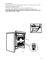
Fig. 44
D
B
PE
A
N
L
230 V
PE
N
L
1
(L
2
)
Fig. 45
Electrical feeder cable connection
To connect the supply cable:
- Remove the screws securing the cover “
A
” on the rear of the cooker (fig. 44).
- Feed the supply cable through the cable clamp “
D
”. The supply cable must be of a
suitable size for the current requirements of the appliance; see the section “Feeder cable
section”.
- Connect the wires to the terminal block “
B
” as shown in the diagram in figure 45; or
connect the phase wires to the terminal block “
B
” and the earth wire to the terminal PE
as shown in figure 44.
- Take up any slack in the cable and secure with the cable clamp “
D
”.
- Replace the cover “
A
”.
Before carrying out any work on the electrical parts of the appliance, the appliance
must first be disconnected from the electrical supply.
Feeder cable section type H05RR-F
230 V
3 x 2,5 mm
2
(**)
(**) – Connection with wall box connection.
Earth cable must be 2 cm longer than neutral and live cables.
Summary of Contents for PZ 10/2
Page 47: ...47 ...

