Installation and Troubleshooting Guide
All rights reserved. Reproduction or use of content, in any manner, without express written permission by CDI Electronics, Inc., is prohibited
.
Page - 4 of 4
QF-319
T E C H N I C A L S E R V I C E BU L L E T I N
Reference Information OMC Outboard Service Bulletin 2276 Rev 1 April 1994
No. 032510
Subject:
Engine Over-Heating
Make:
Johnson & Evinrude
Horsepower: 50 HP
60 HP
65 HP
70 HP
Years:
1986-94
1986-94
1987-94
1989-94
Problem: The engine and electrical system can become damaged due to over-heating when air is trapped in the upper
half of the cooling system. Trapped air can cause the upper cylinder or regulator/rectifier to overheat, resulting
in damage to the piston or the regulator/rectifier (possibly burning out and damaging the stator also).
Air can become trapped when:
1.
The engine is idling with a blocked or restricted thermostat bypass hole.
2.
The engine is operated in aerated water, such as a pontoon or deck boat wakes.
Solution: Relocate the water pump indicator outlet tee (for the pee tube) from the side of the engine block to the top of
the engine block. This allows air to be vented from the top of the cooling system and helps ensure an adequate
water level when idling.
If the engine does not have a threaded hole located in the top of the cylinder block, please follow the steps below:
1.
Remove the indicator hose from the outlet tee and discard it.
2.
Remove the outlet tee.
3.
Install a 1/8
th
NPT Brass pipe plug into the hole where the tee was located (use Gelseal on the threads).
4.
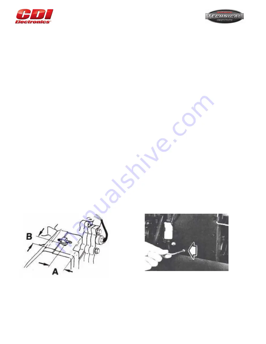
Measure 2 inches forward from the rear corner of the exhaust manifold cover( ref “A”) and 1-3/8 inches from the
exhaust cover gasket (ref “B”. Mark the intersection with a center punch (see figure 2).
5.
Mark an 11/32
nd
(Letter “R”) drill bit ½ inch from the tip (to prevent damage to the water jacket) as a depth gauge.
Grease the tip of the drill bit and drill a hole through the casting. The grease will help prevent metal shavings from
entering the cooling system.
6.
Grease the tip of an 1/8 inch NPT tap and thread the hole. Be careful to not over tap the hole (over tapping may
not allow the adapter from sealing off).
7.
Apply Gel Seal to the threads of the original tee and install it into the hole you just tapped. Position the tee so the
nipple is facing the rear of the engine.
8.
Install a new piece of 3/16
th
rubber hose (19 inches long) from the tee to the indicator.


